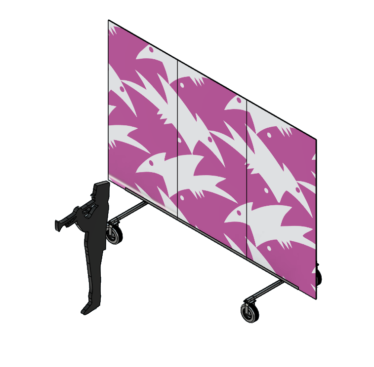
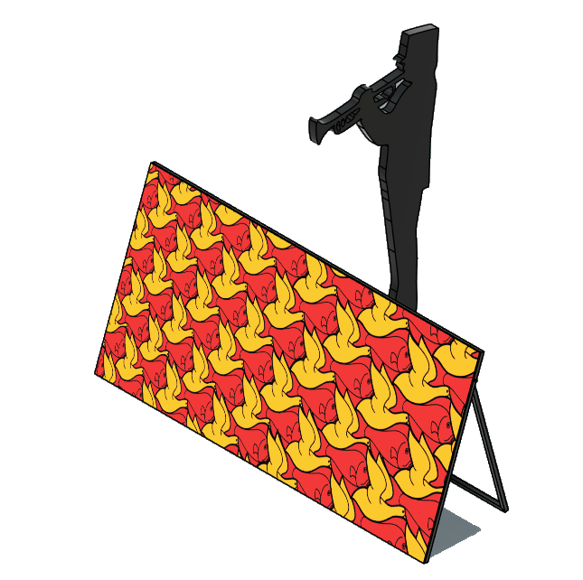
2026 Marching Band Props

Mobile stair & slide platforms

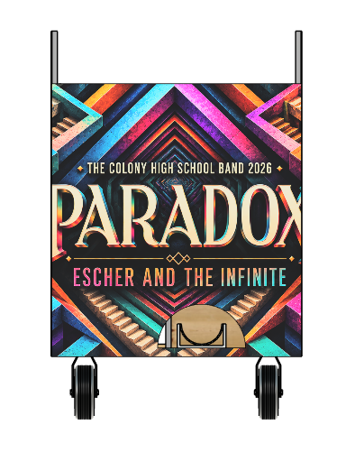
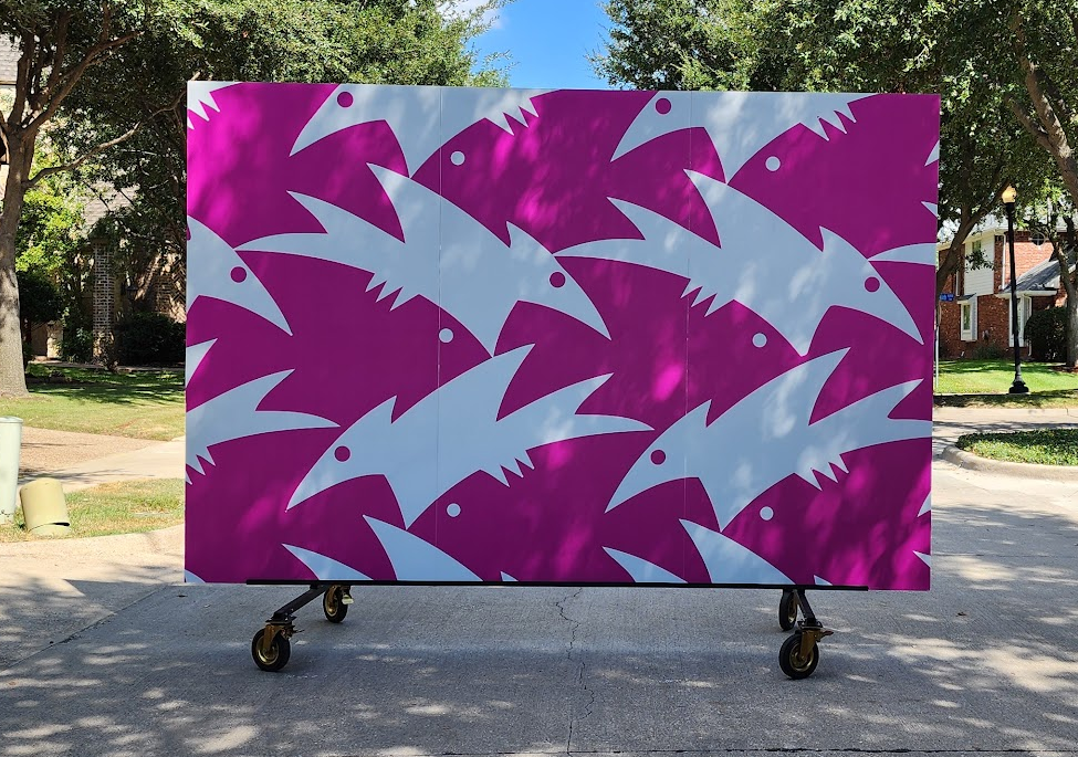
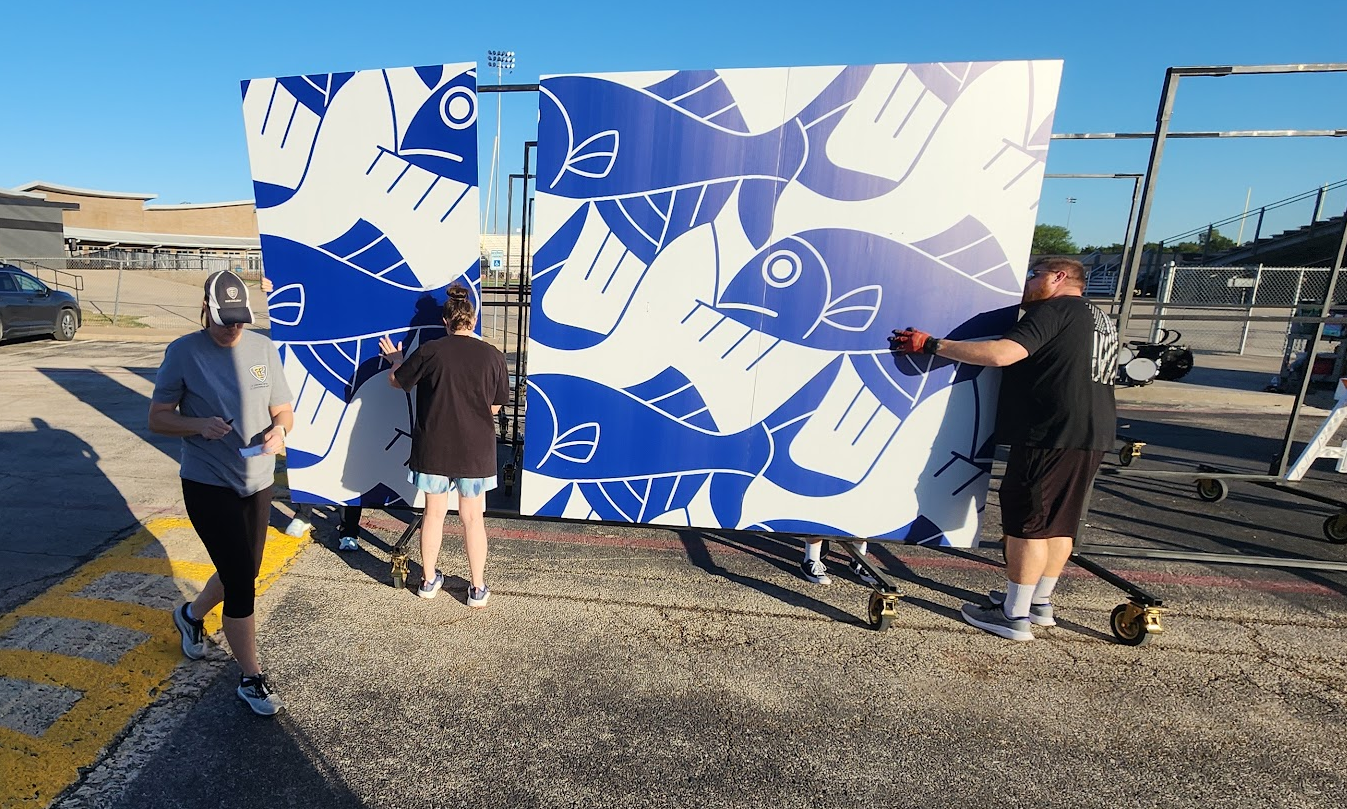
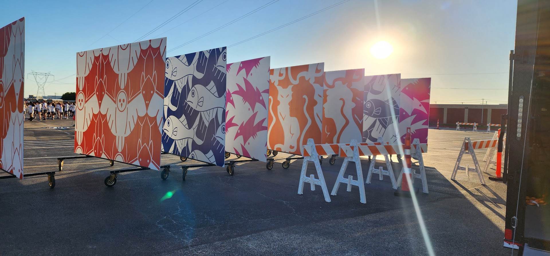
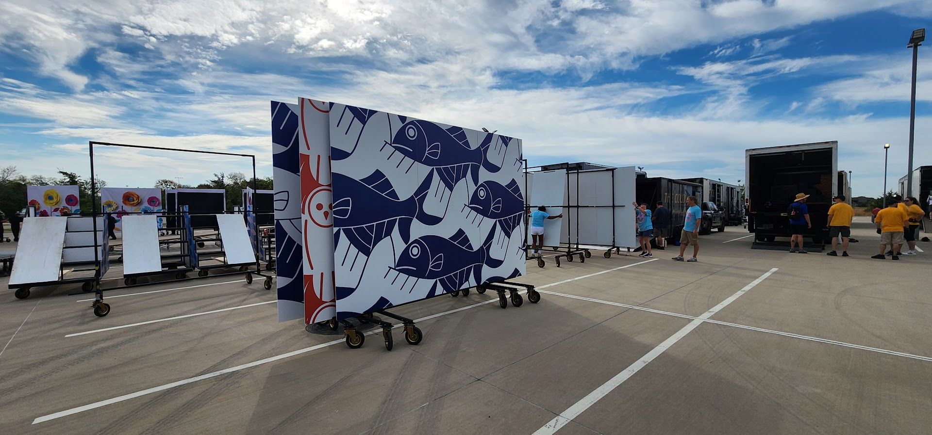
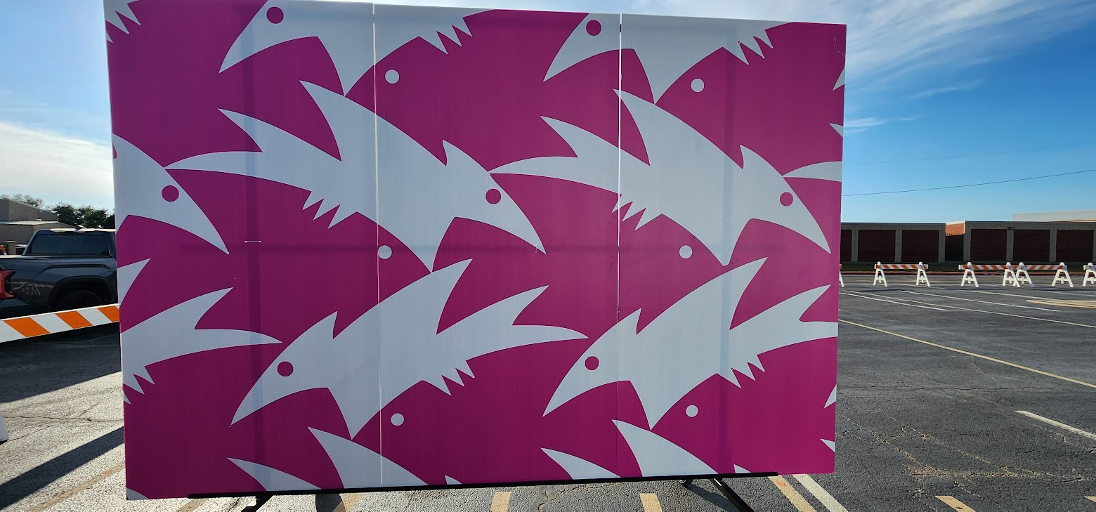
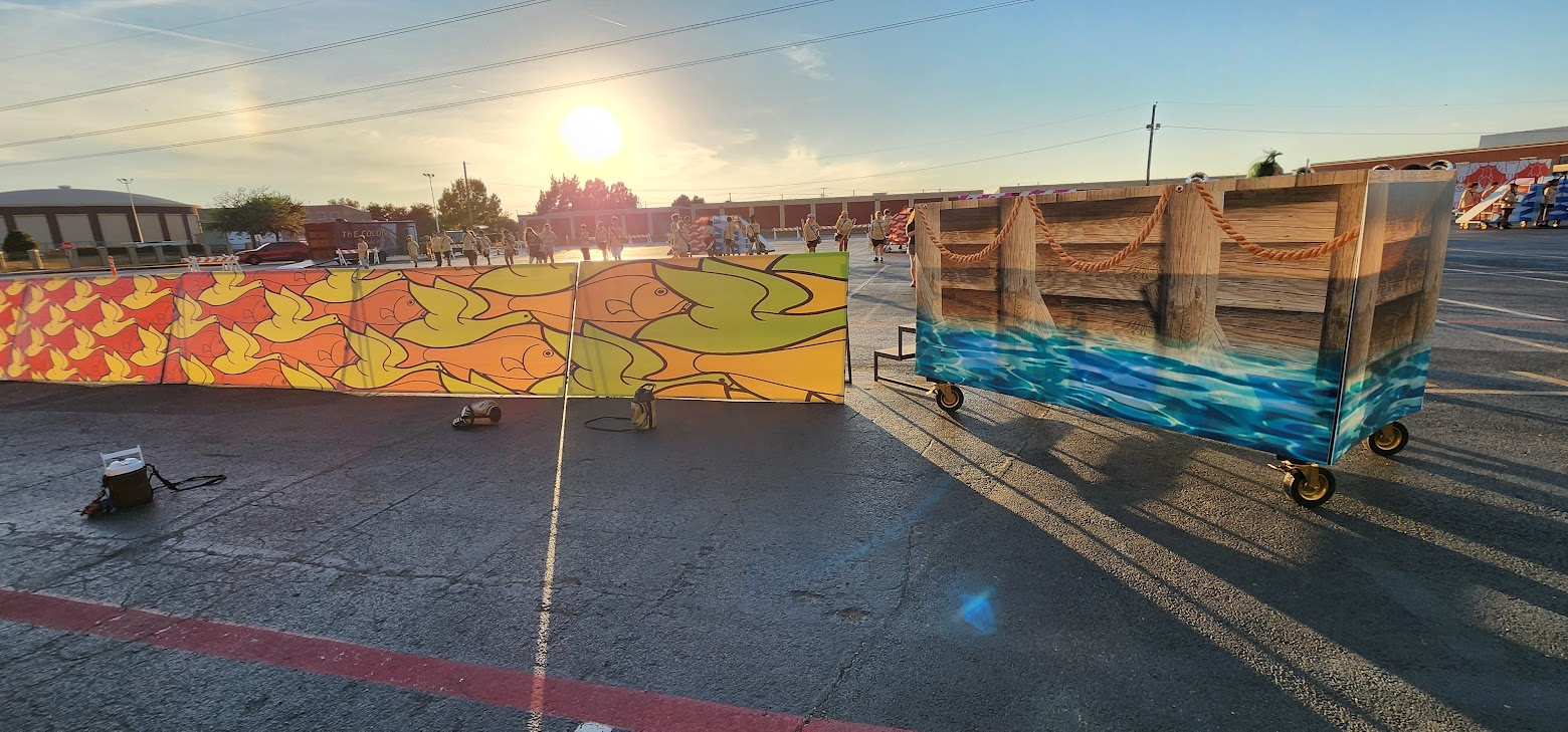
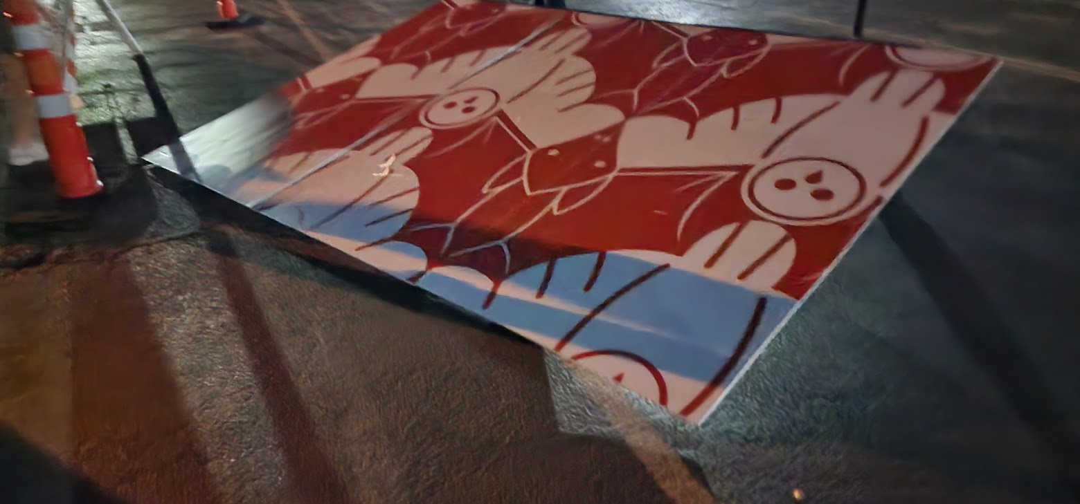
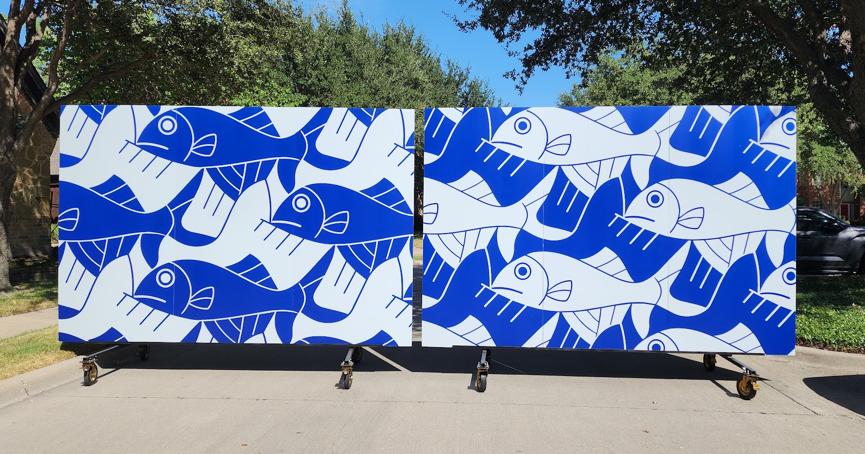
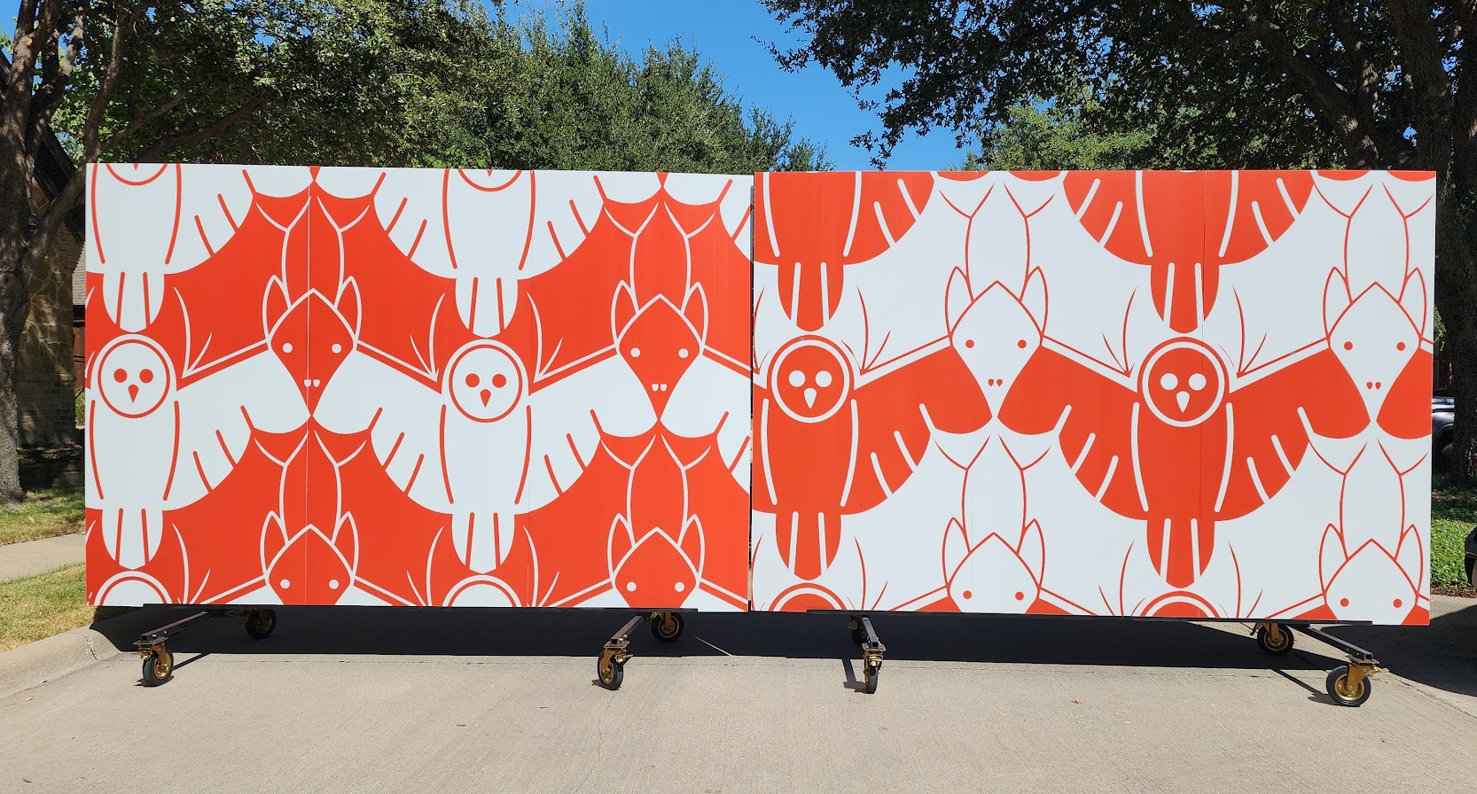
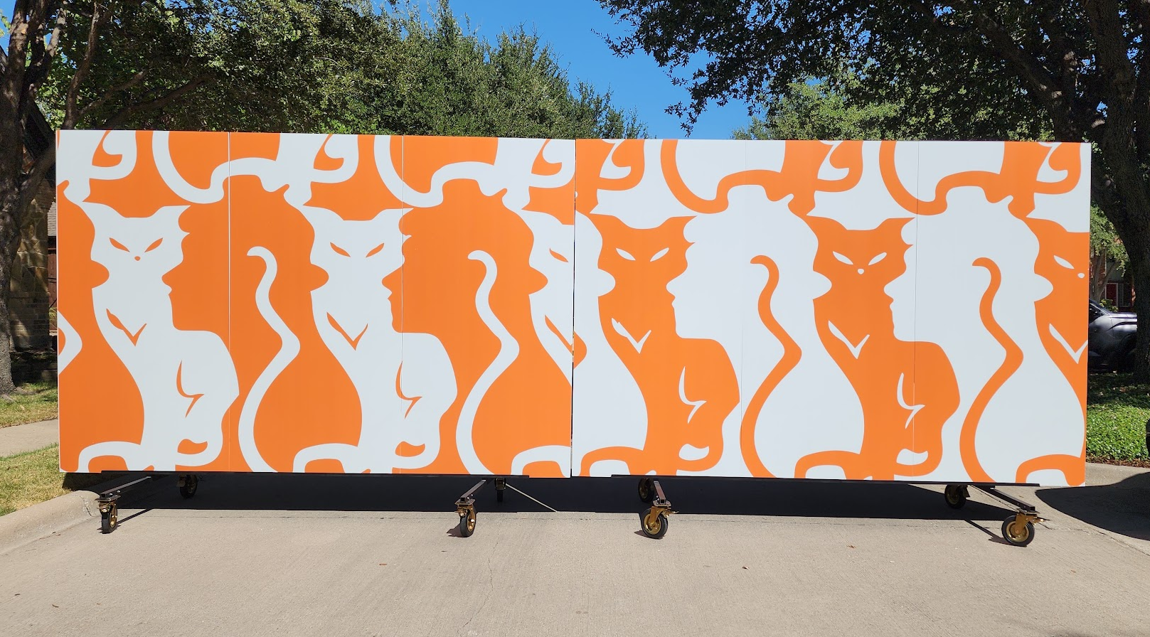
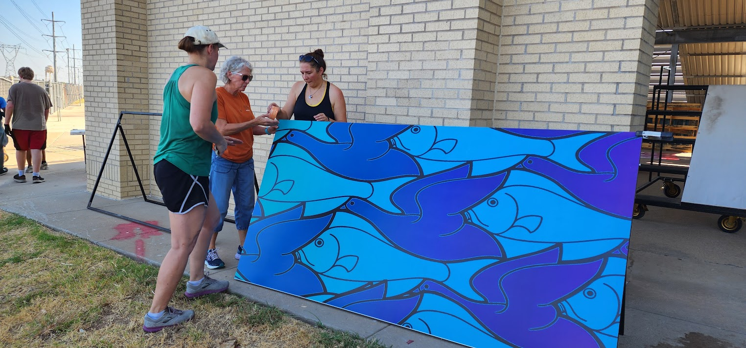
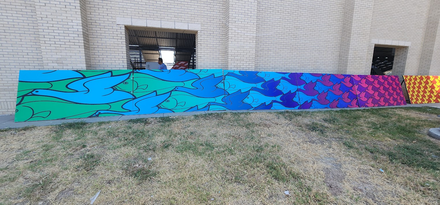
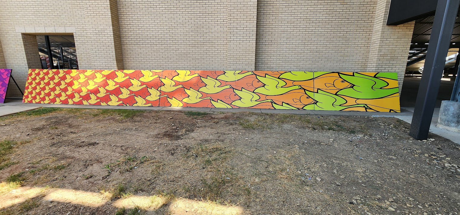
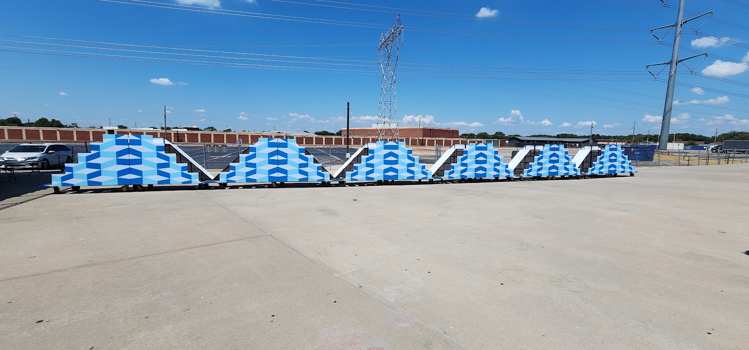
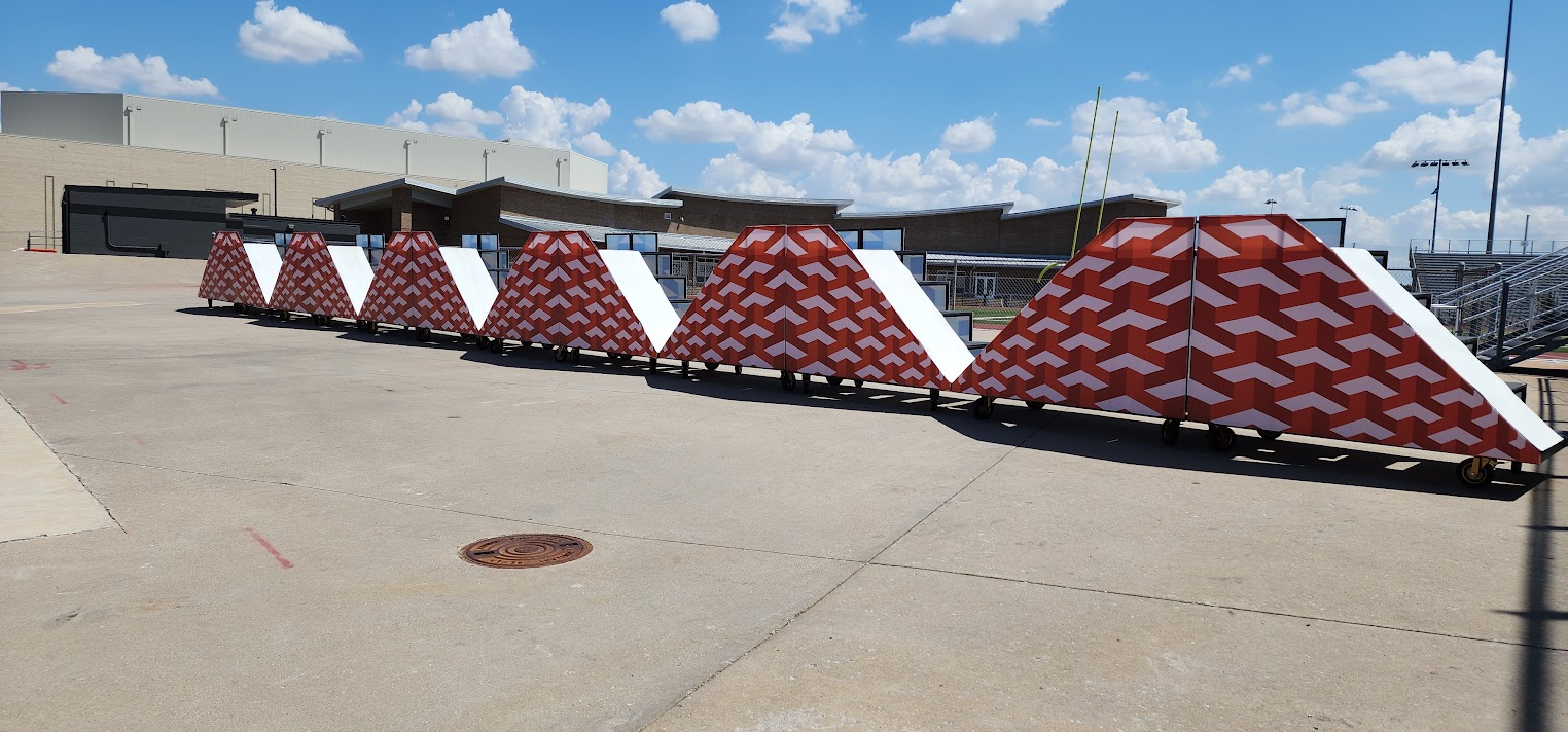
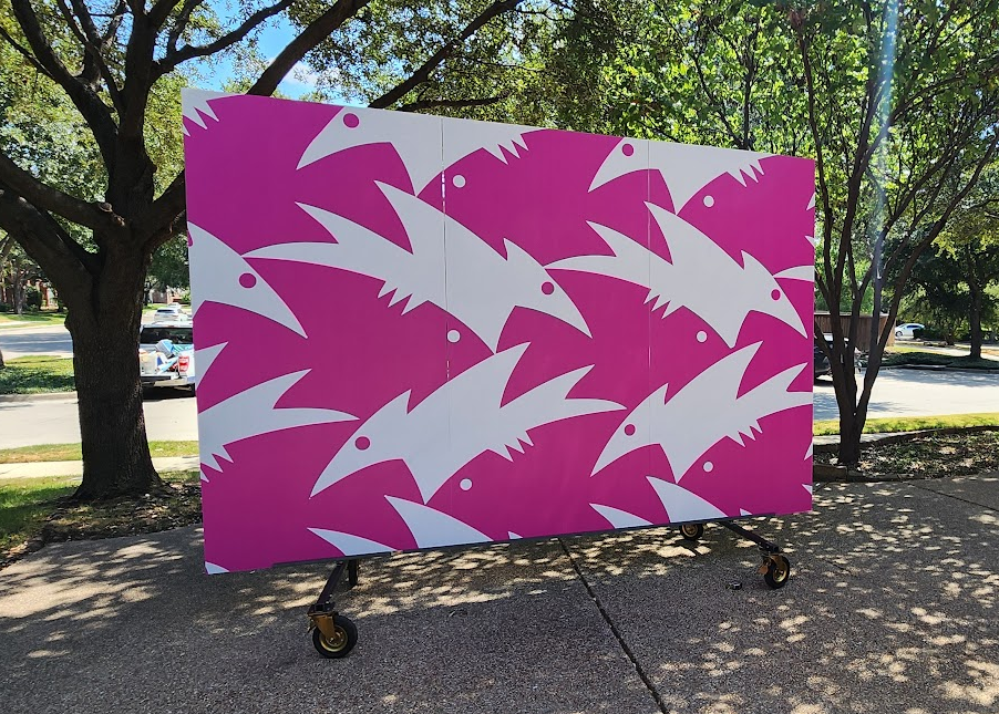
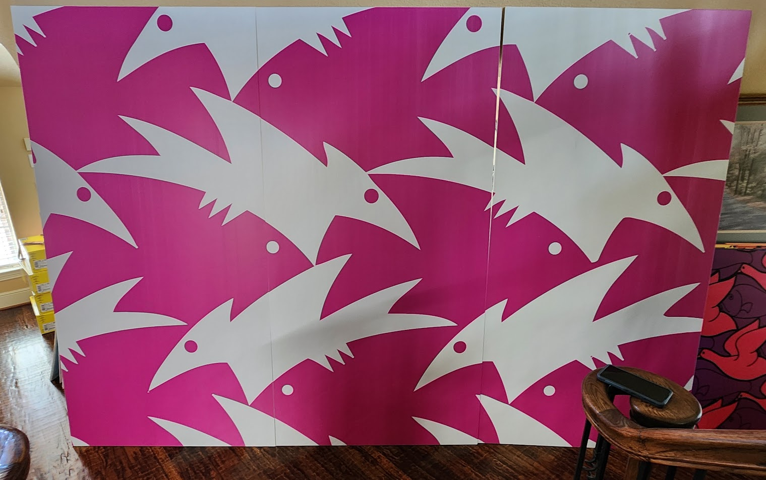
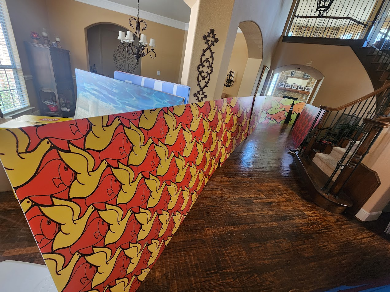
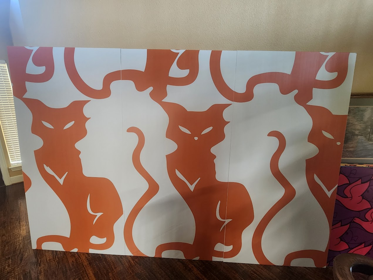
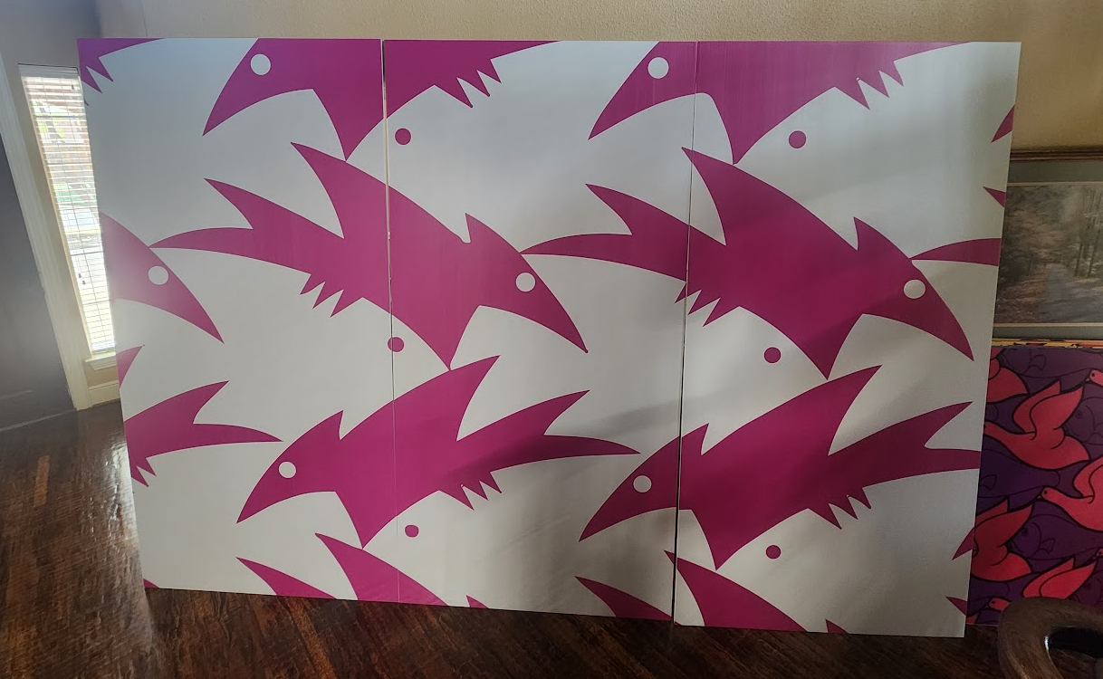
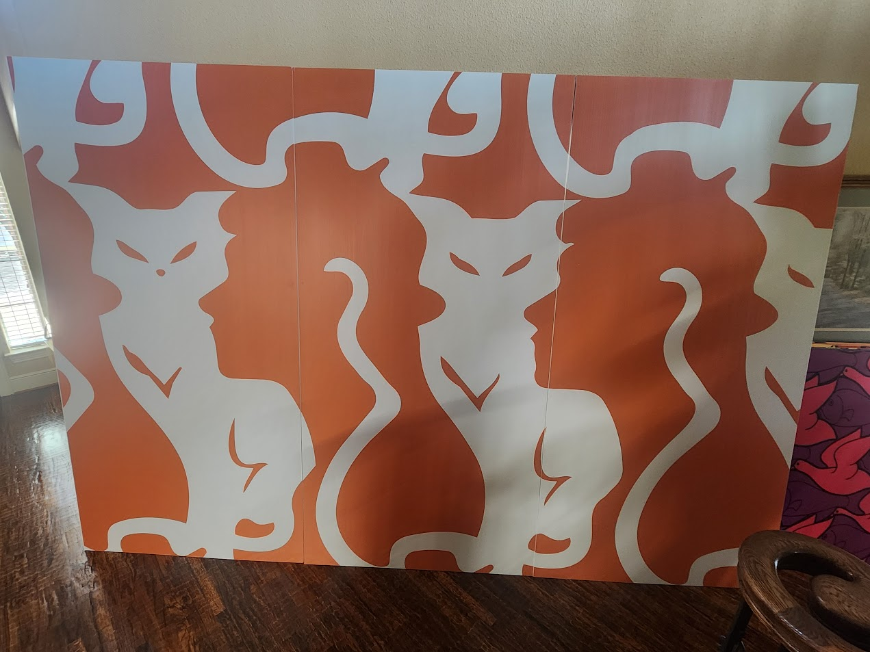
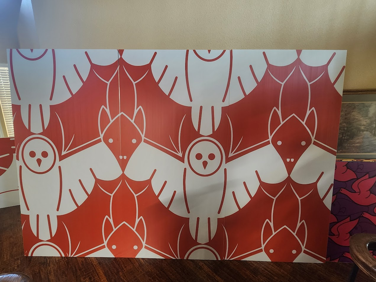
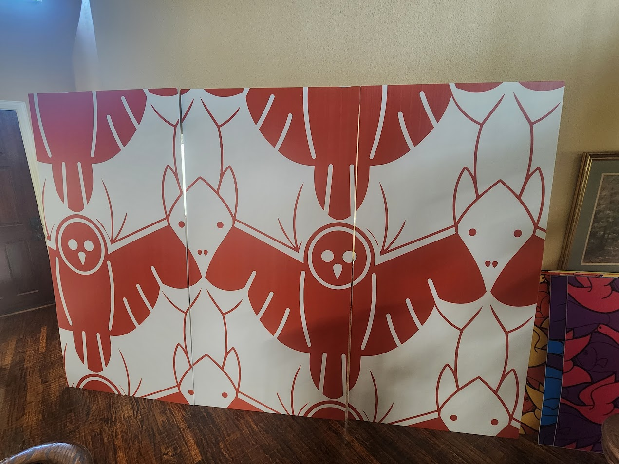
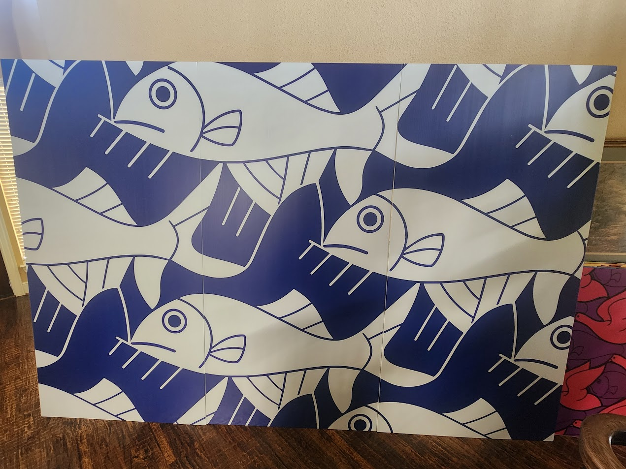
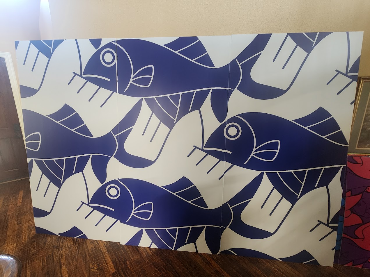
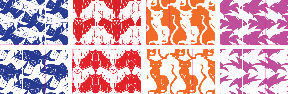
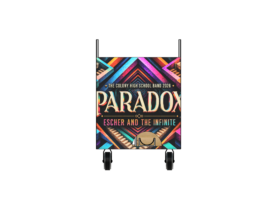
2026 show artwork: Paradox
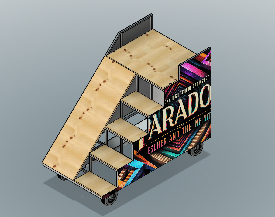
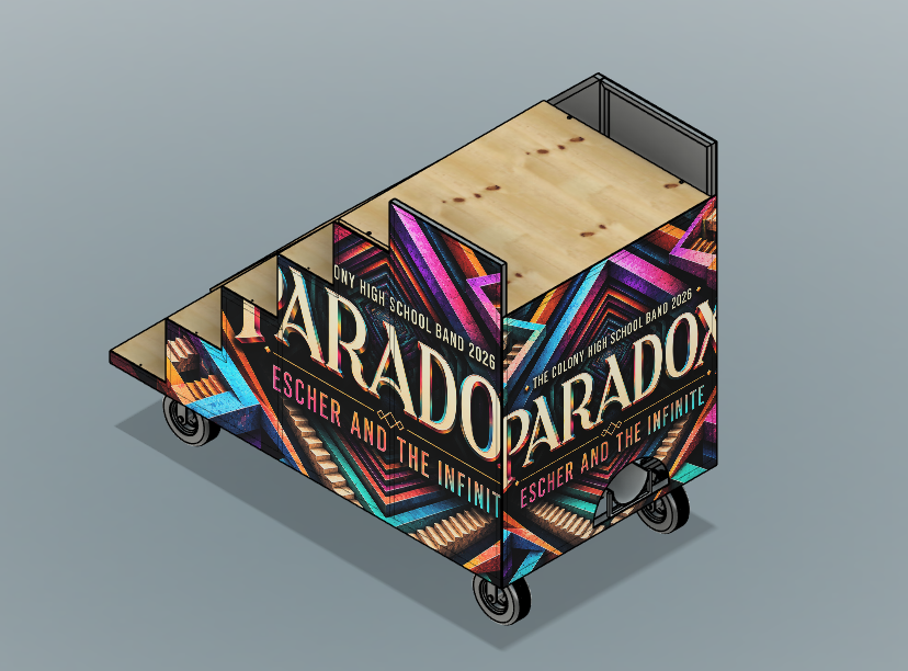
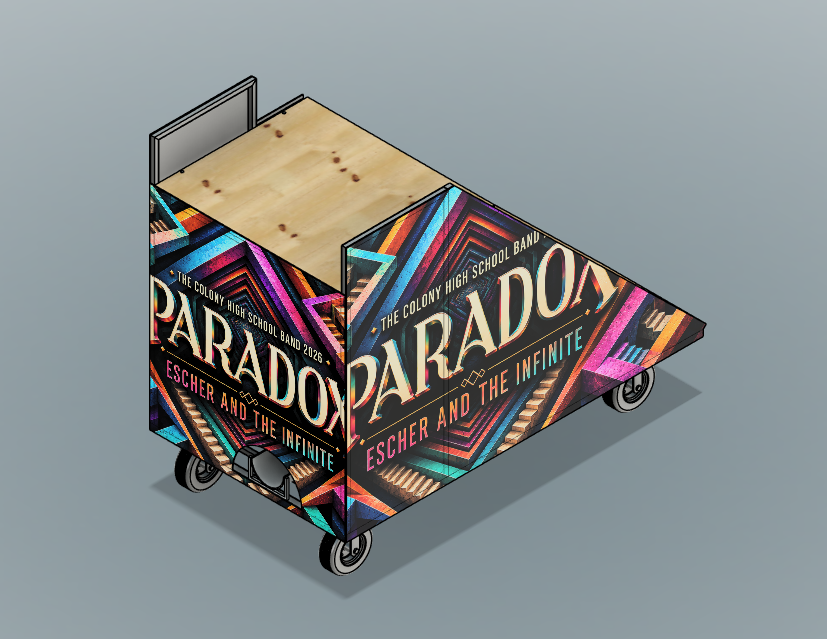
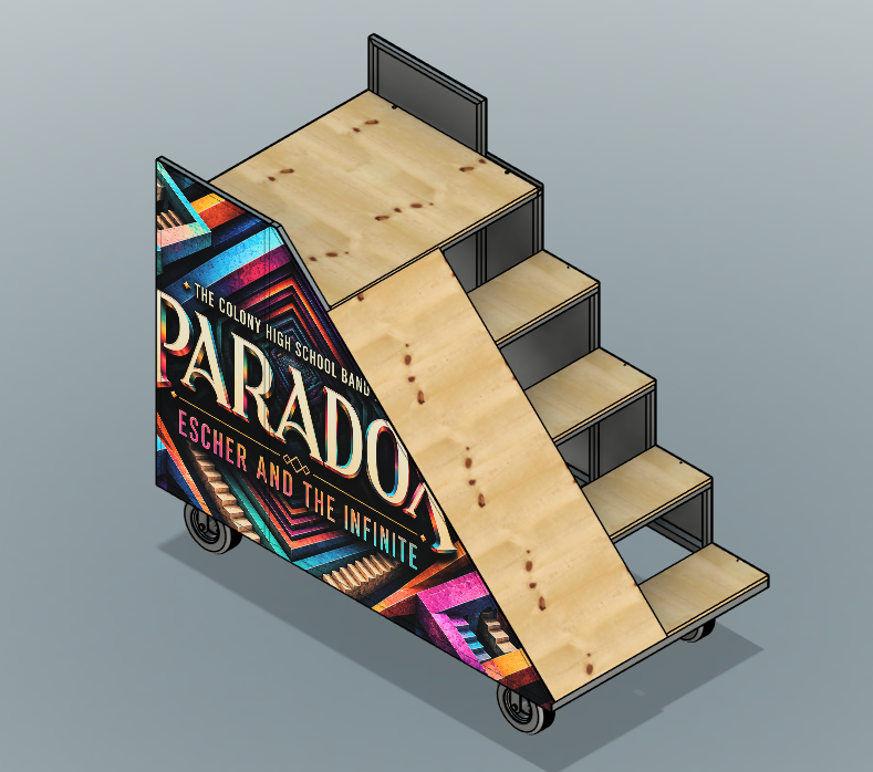
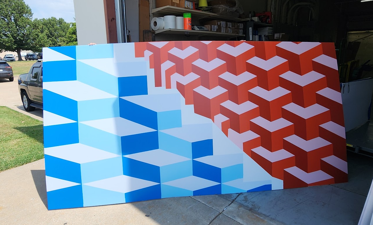
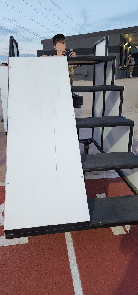
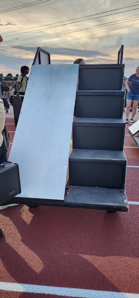
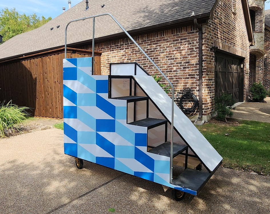
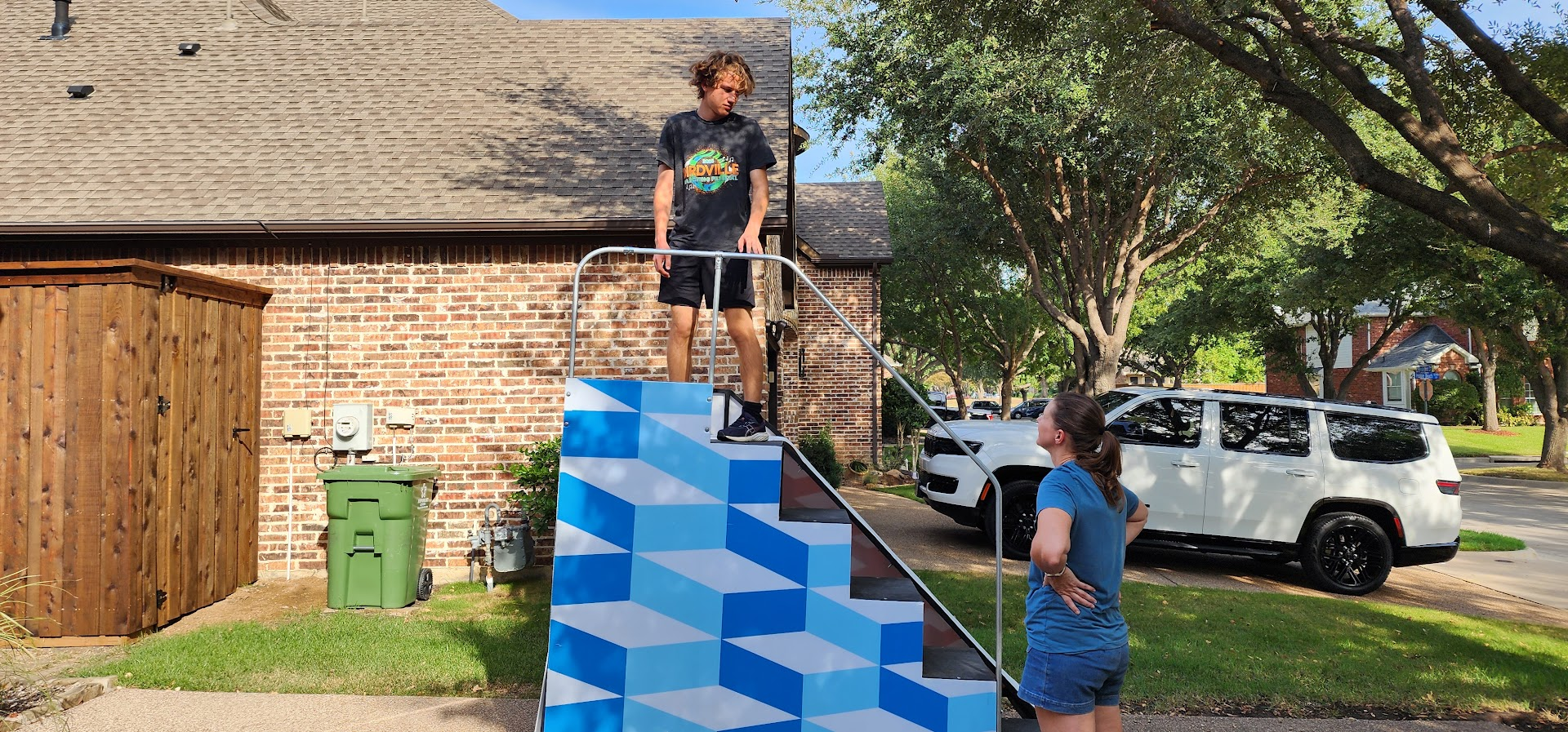
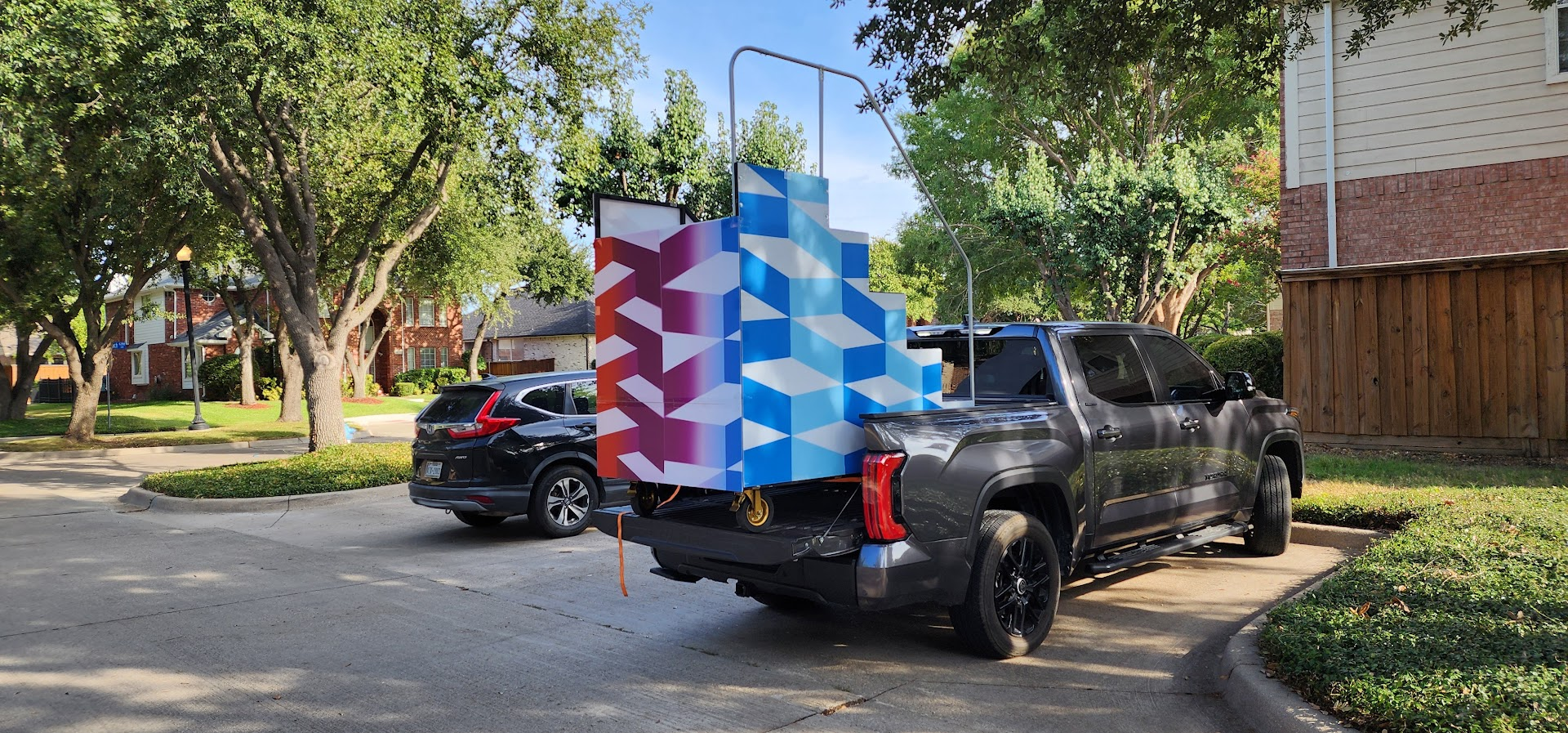
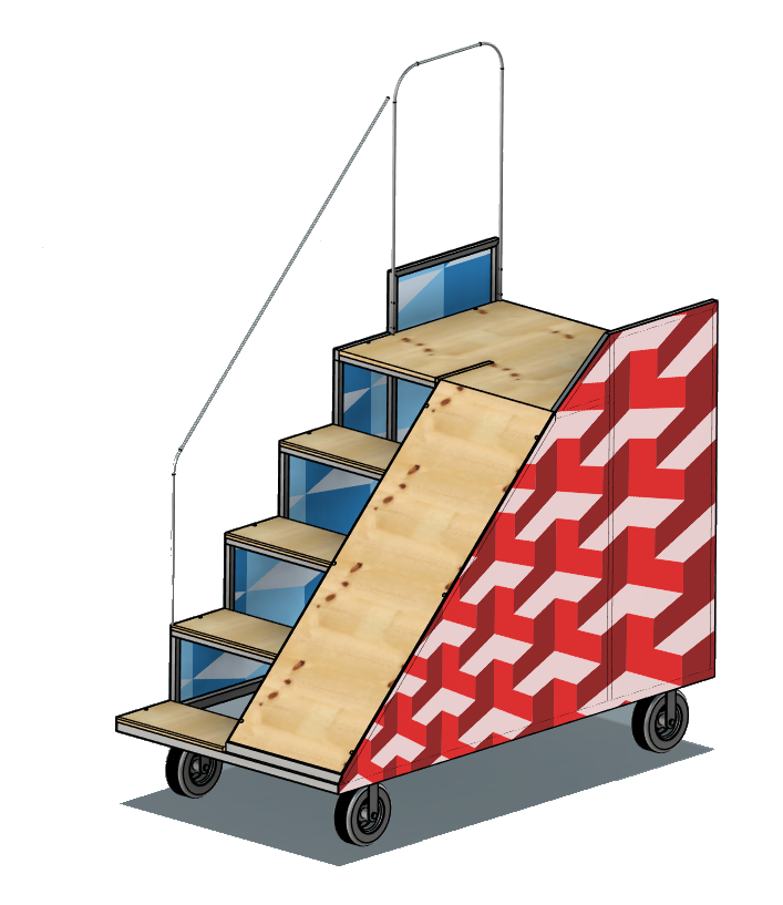
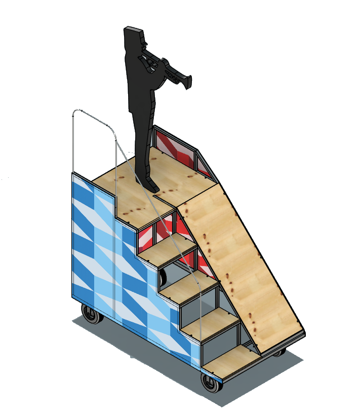
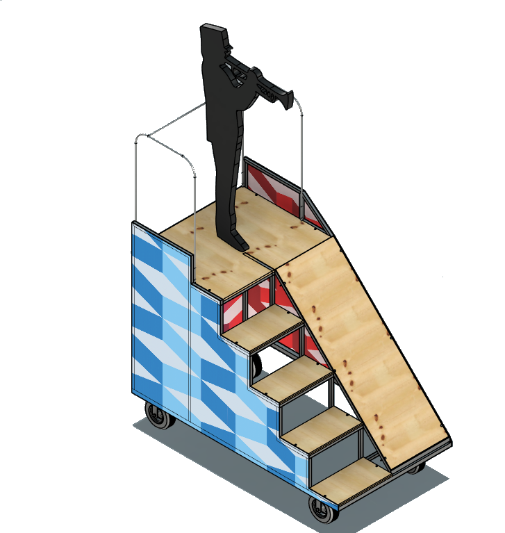
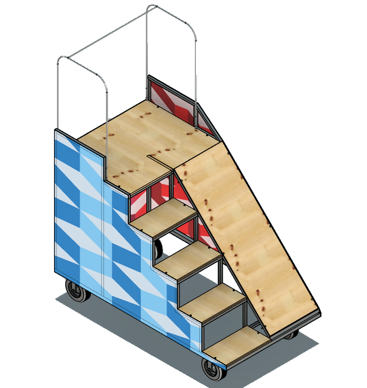
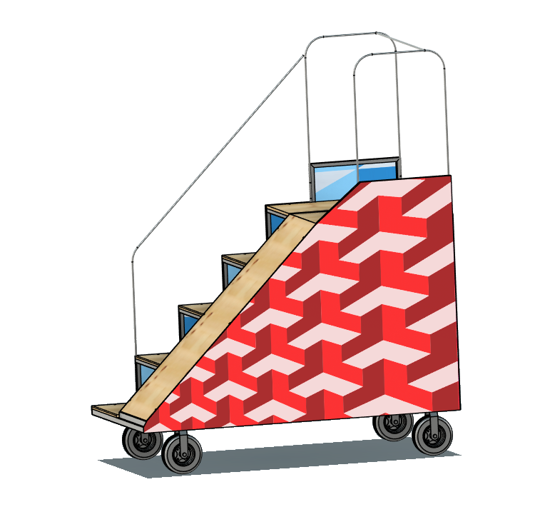
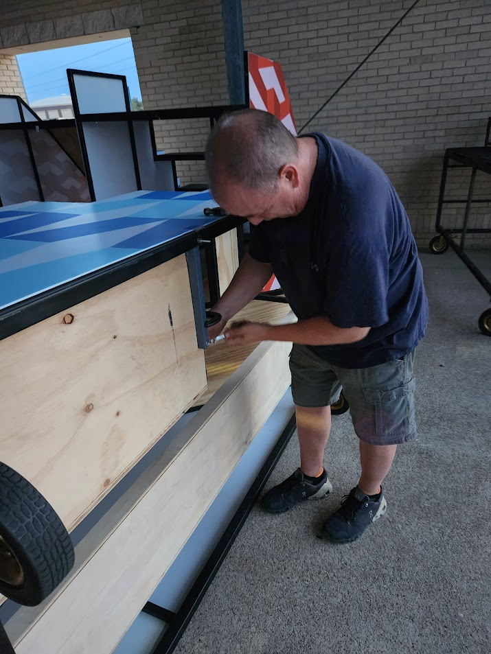
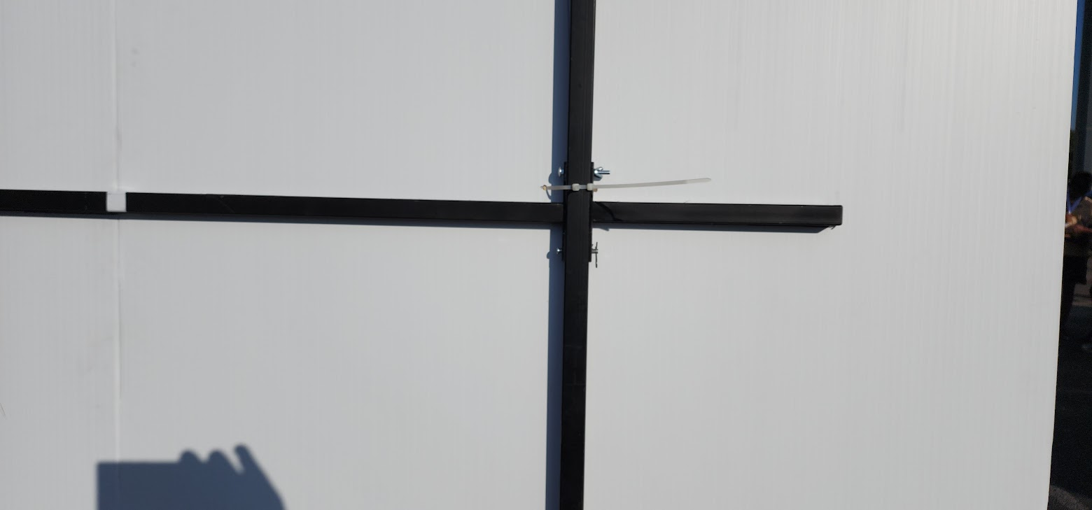
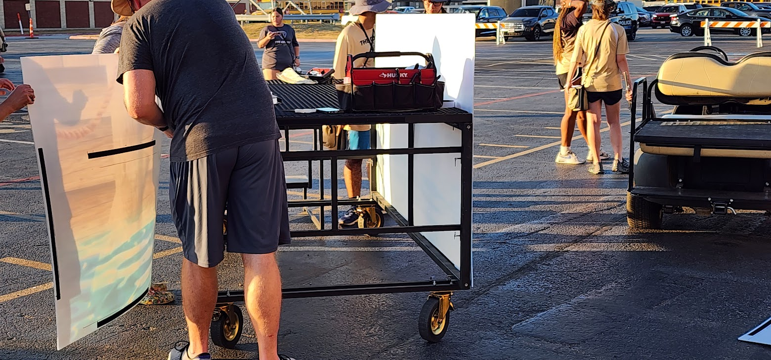
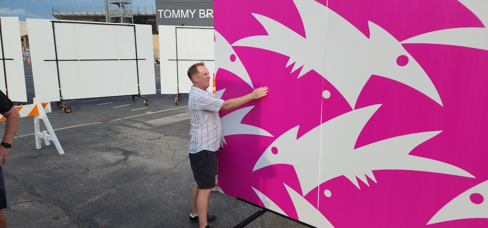
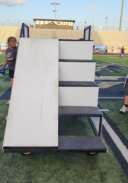
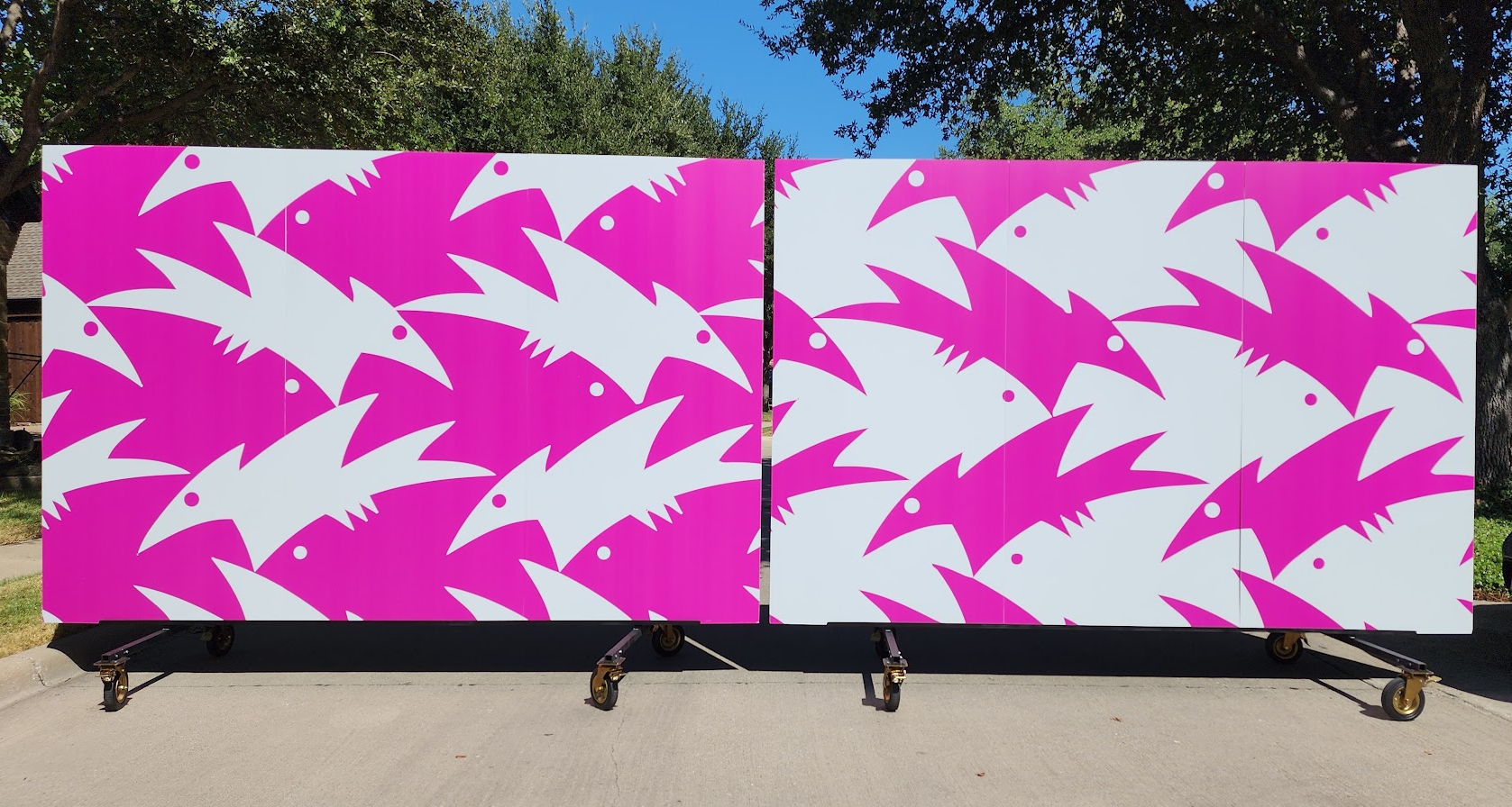
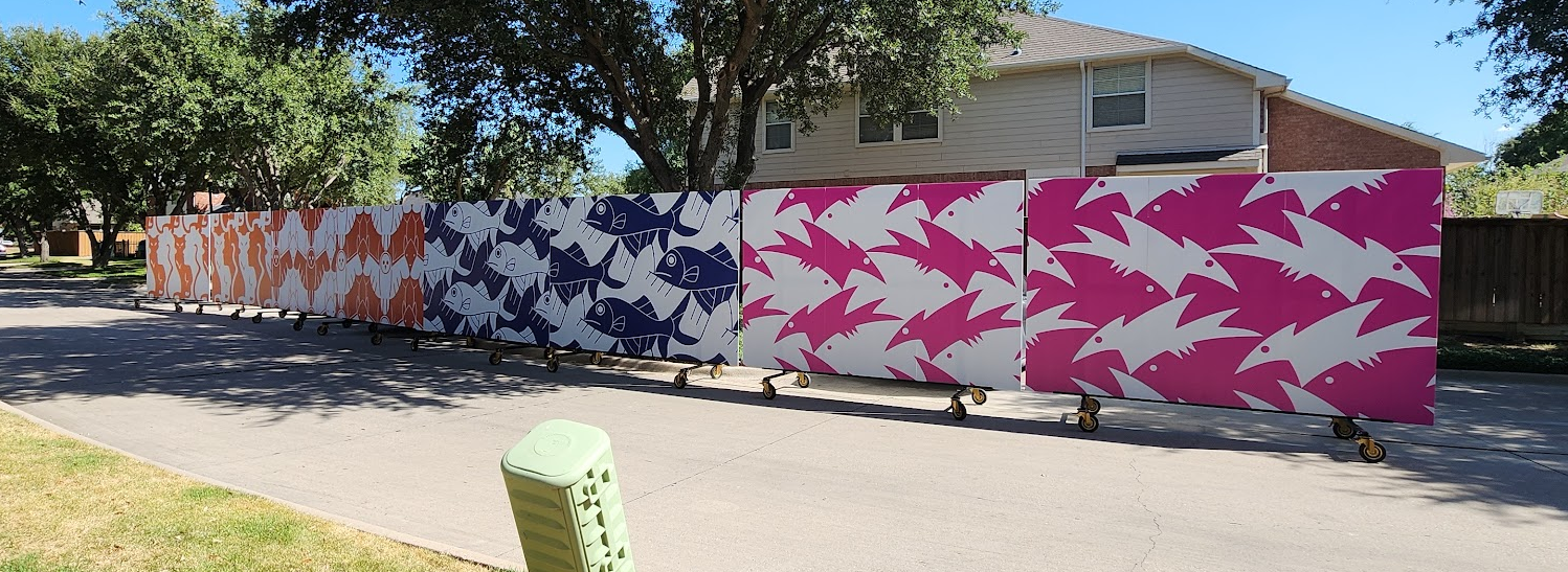
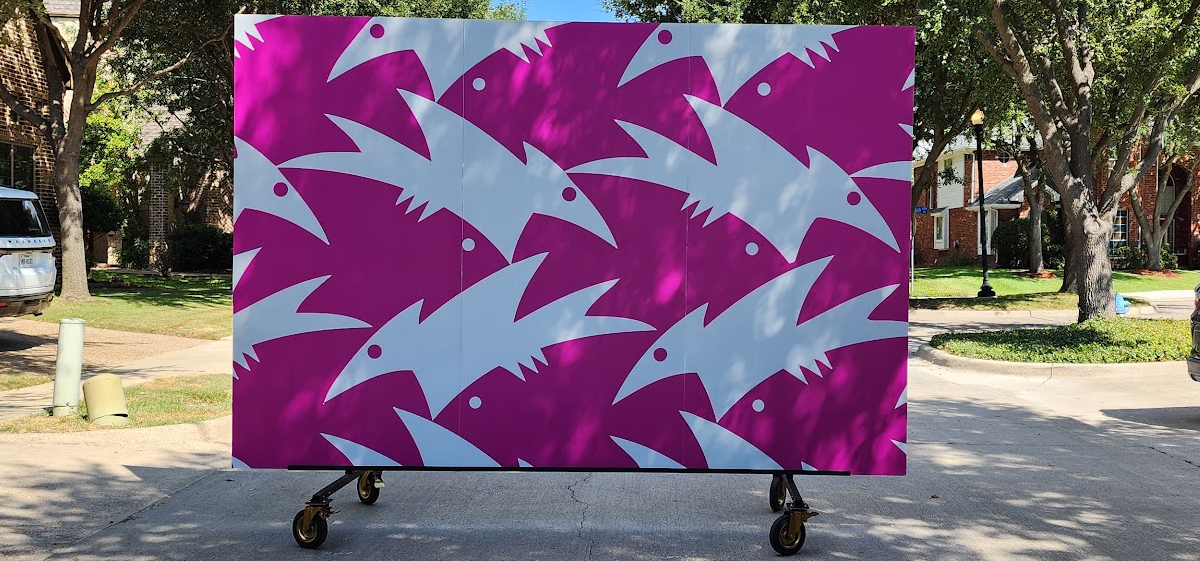
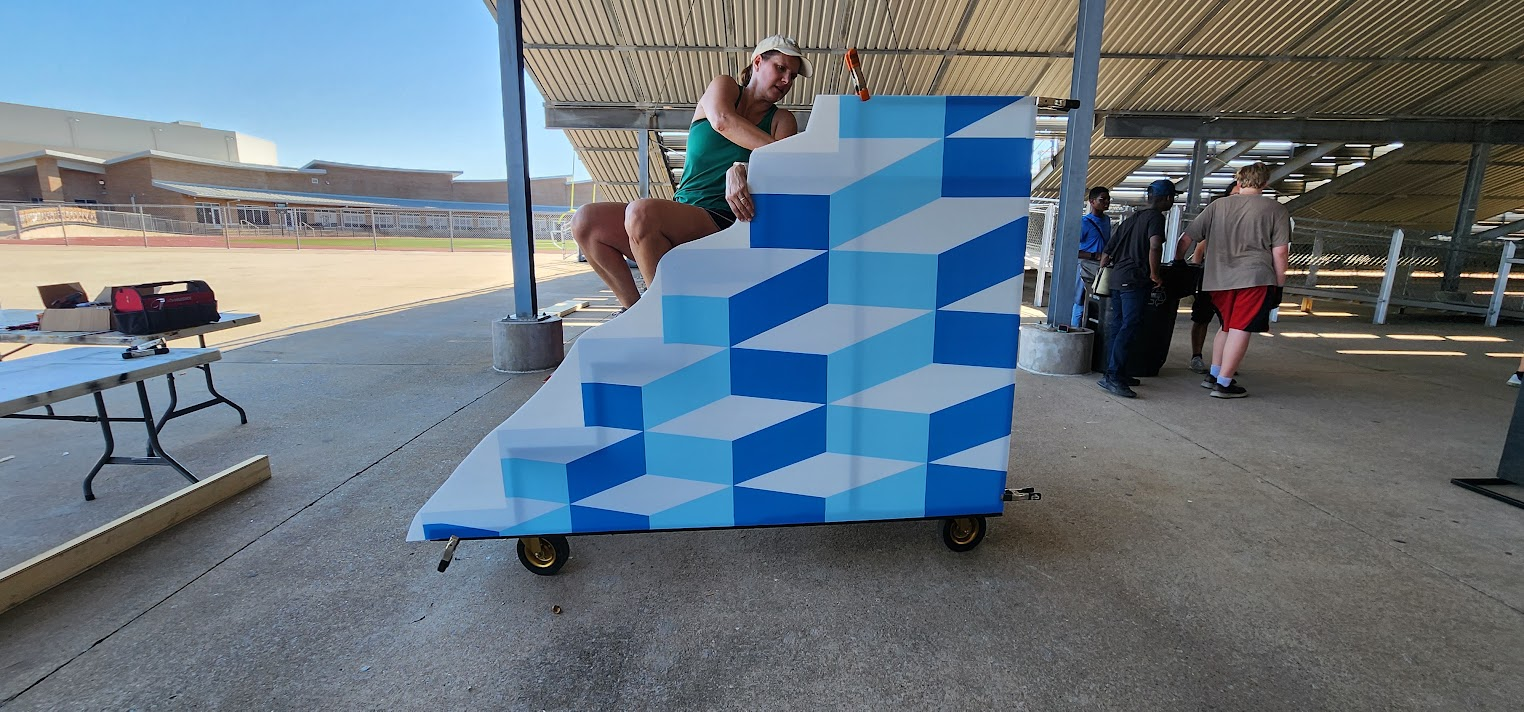
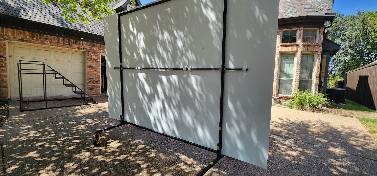
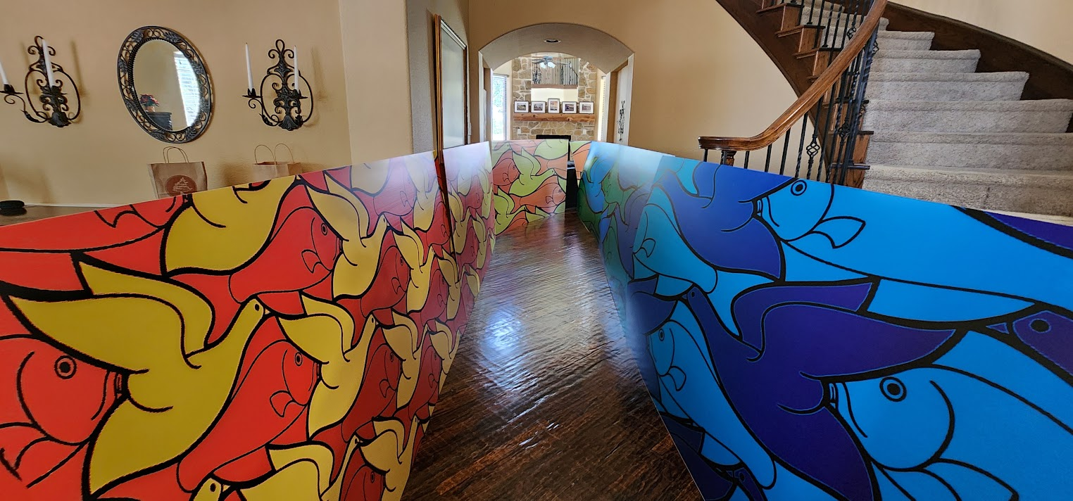
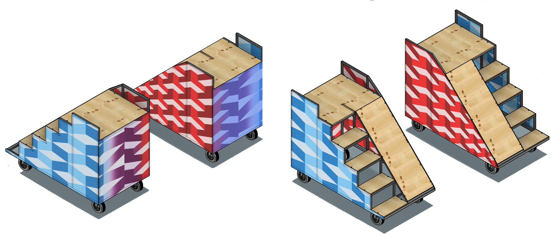
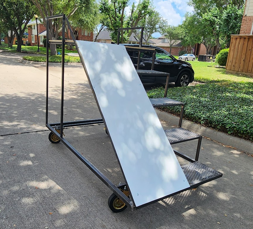
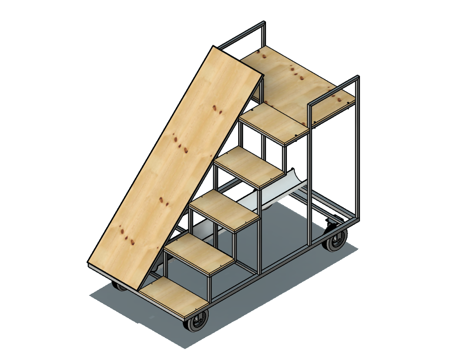
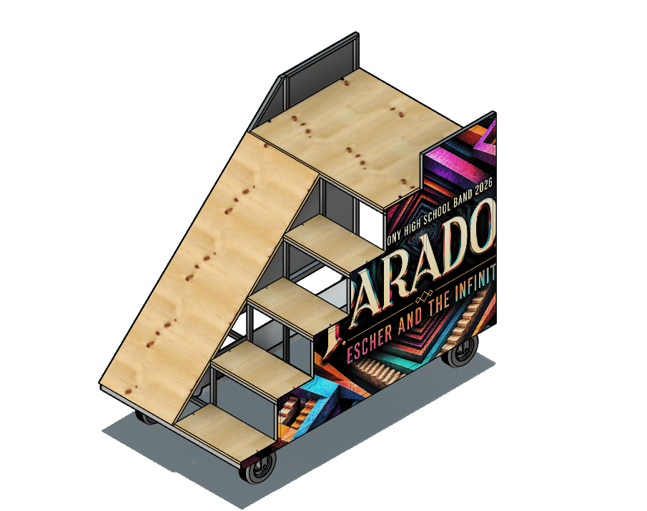
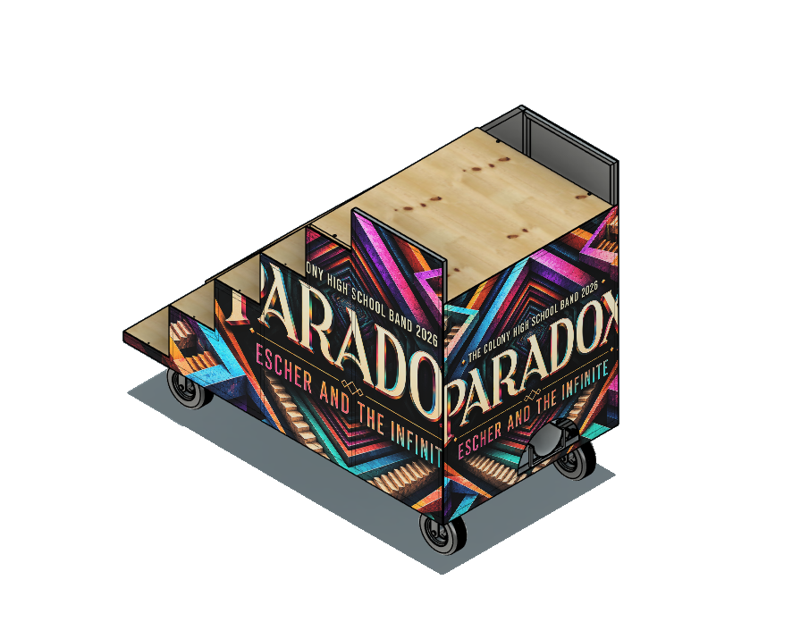
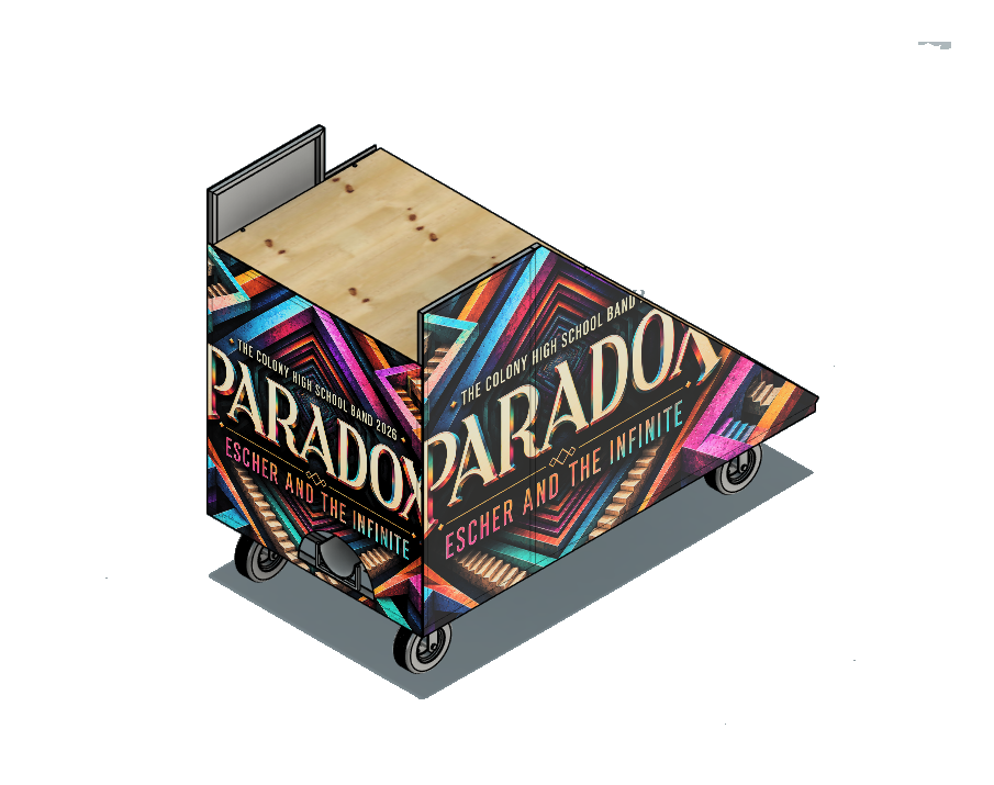
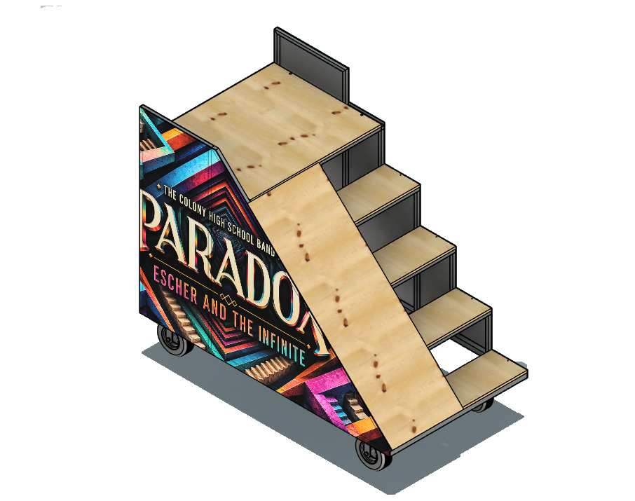
version 2 coroplast mockup, view 1

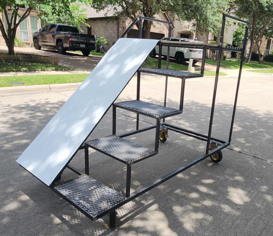
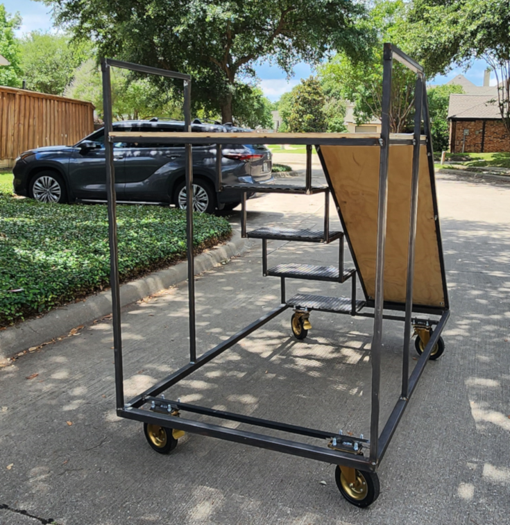
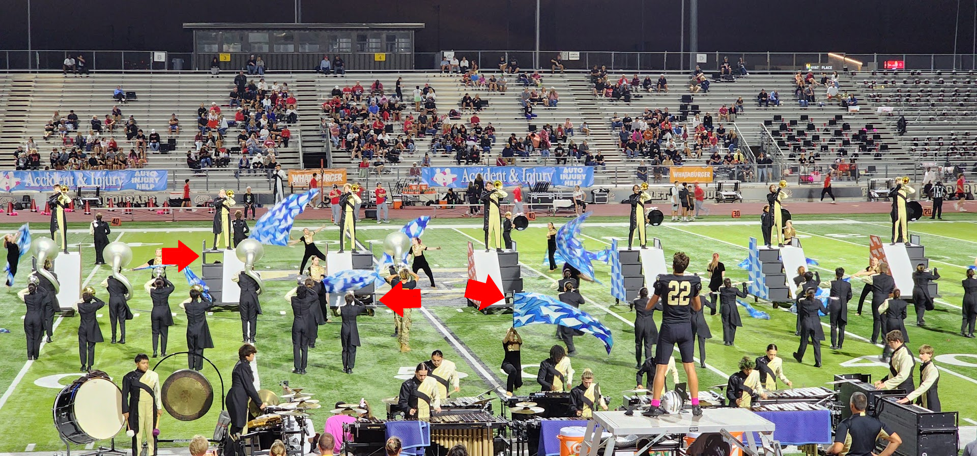
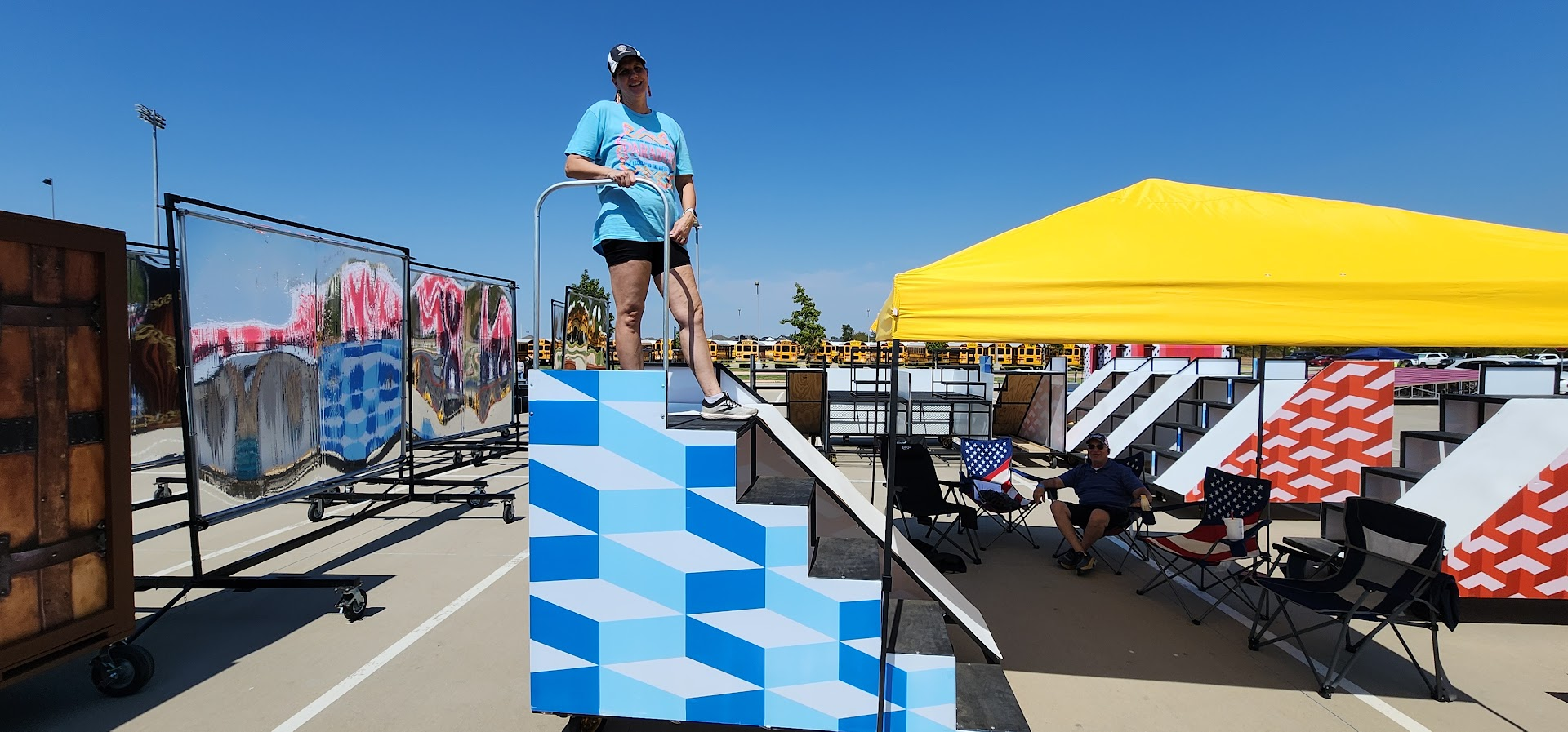
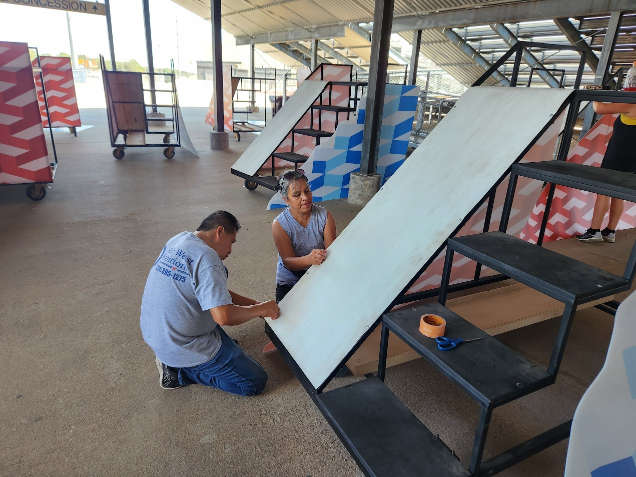
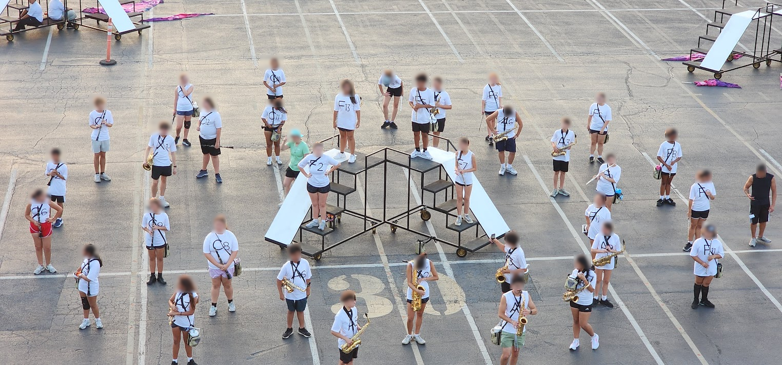
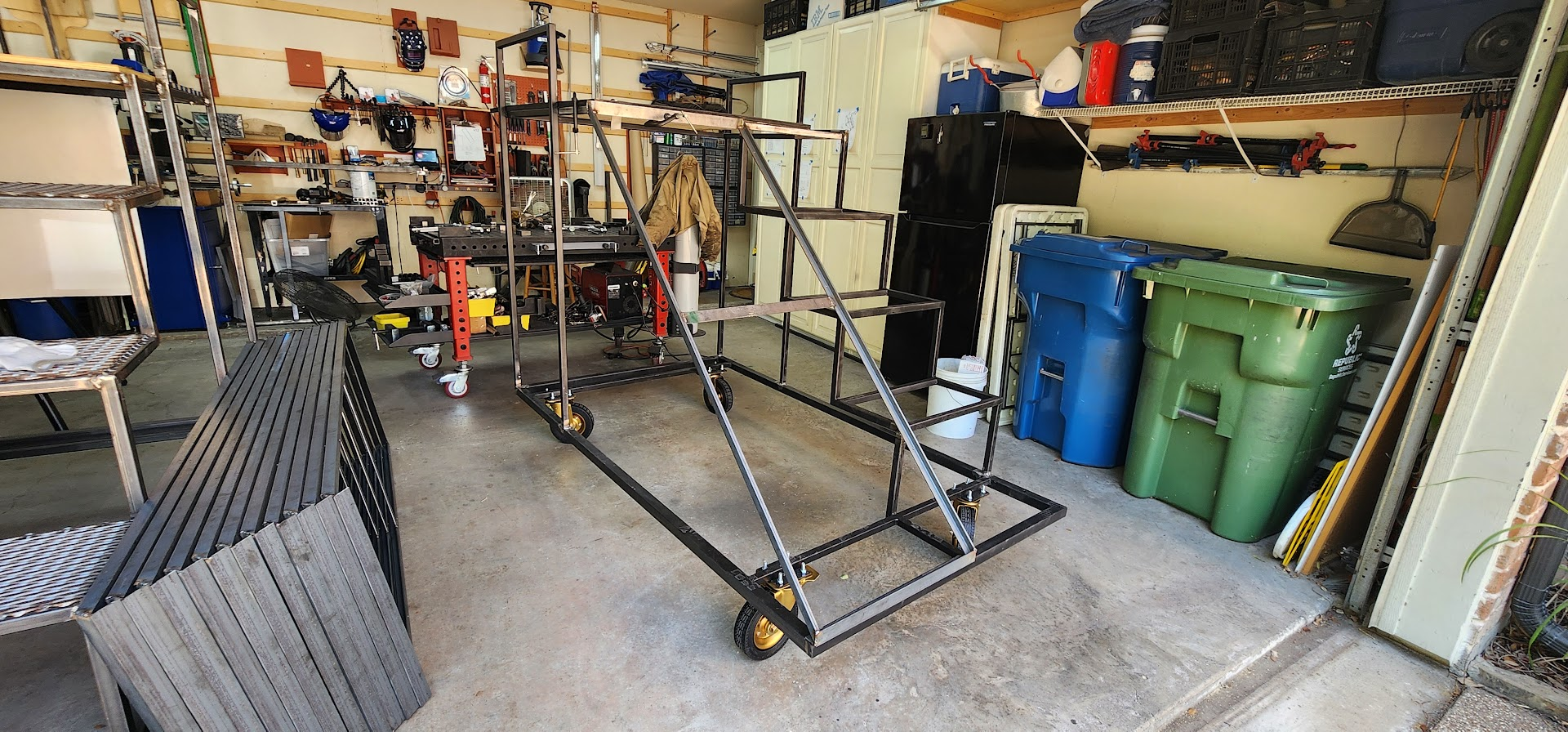
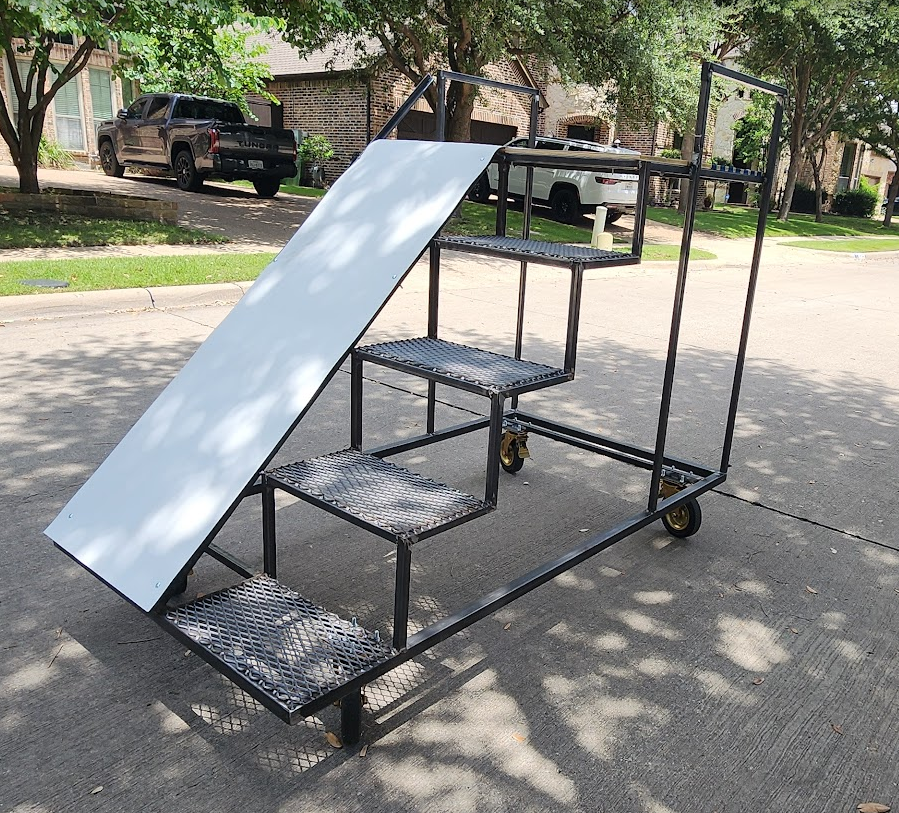
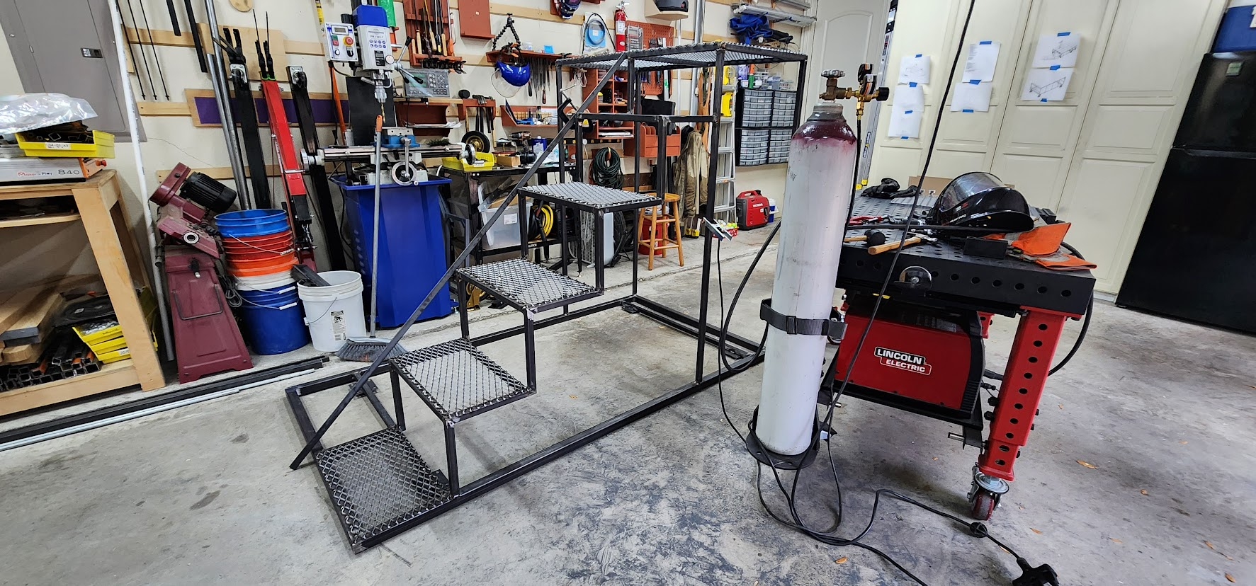
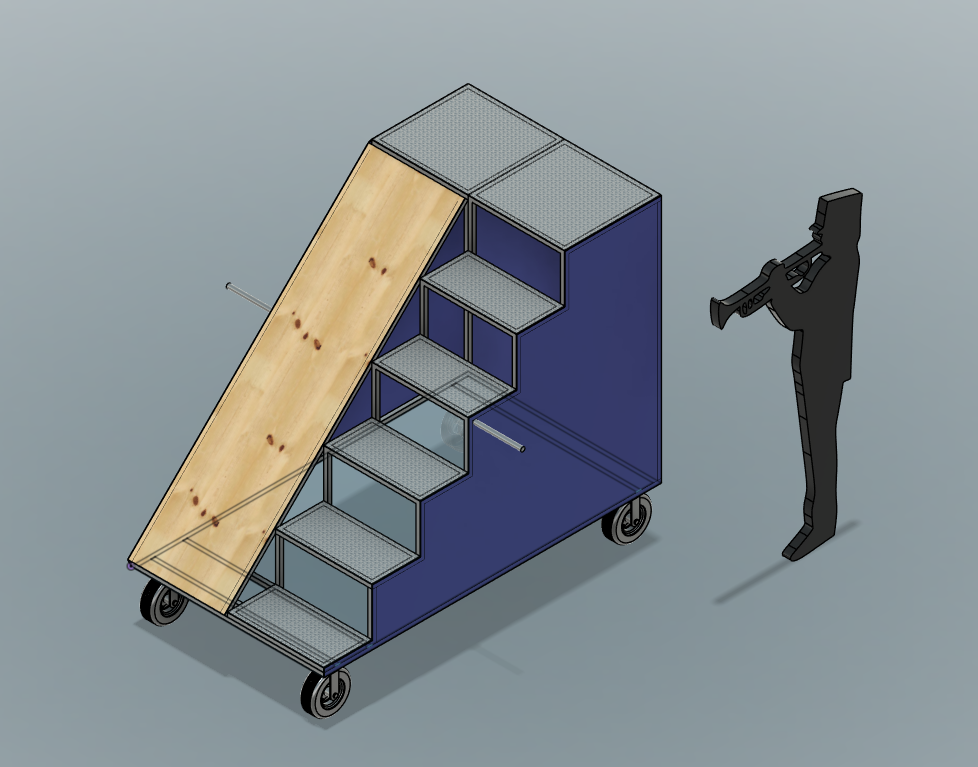
This page tracks the 2026 field show, Paradox—inspired by M. C. Escher’s impossible-perspective drawings—which is why the primary props are mobile staircases: each unit combines a short staircase, a working platform, and a slide on a wheeled steel frame.

This is my final season as a band parent and props lead, so I’m trying to document not just what we build, but how the design decisions get made.

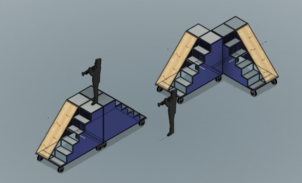
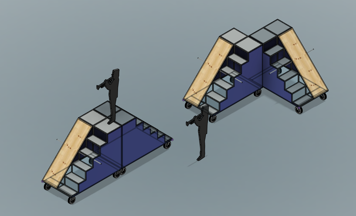
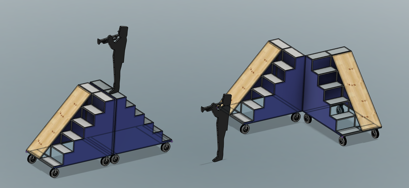
The units are designed to work on their own or be staged together, including configurations where platforms meet at a corner to create a larger performance surface.

Prototype trials refined the design through May 2026; final CAD is complete and build begins in June. I’ll document what works, what doesn’t, and how things evolve here and on the Maker At Play blog.

All props on the field

June 2026 — final CAD layout for the full show set.

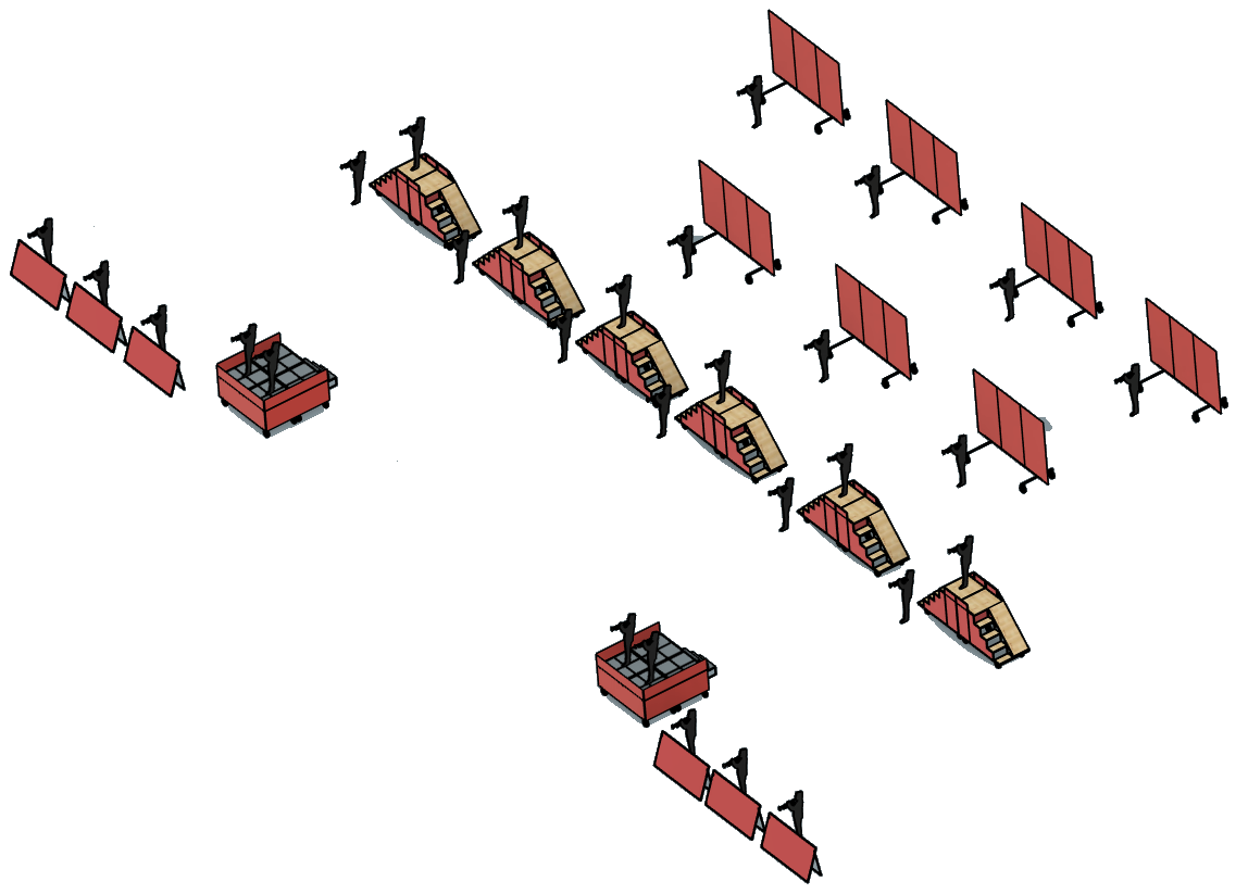
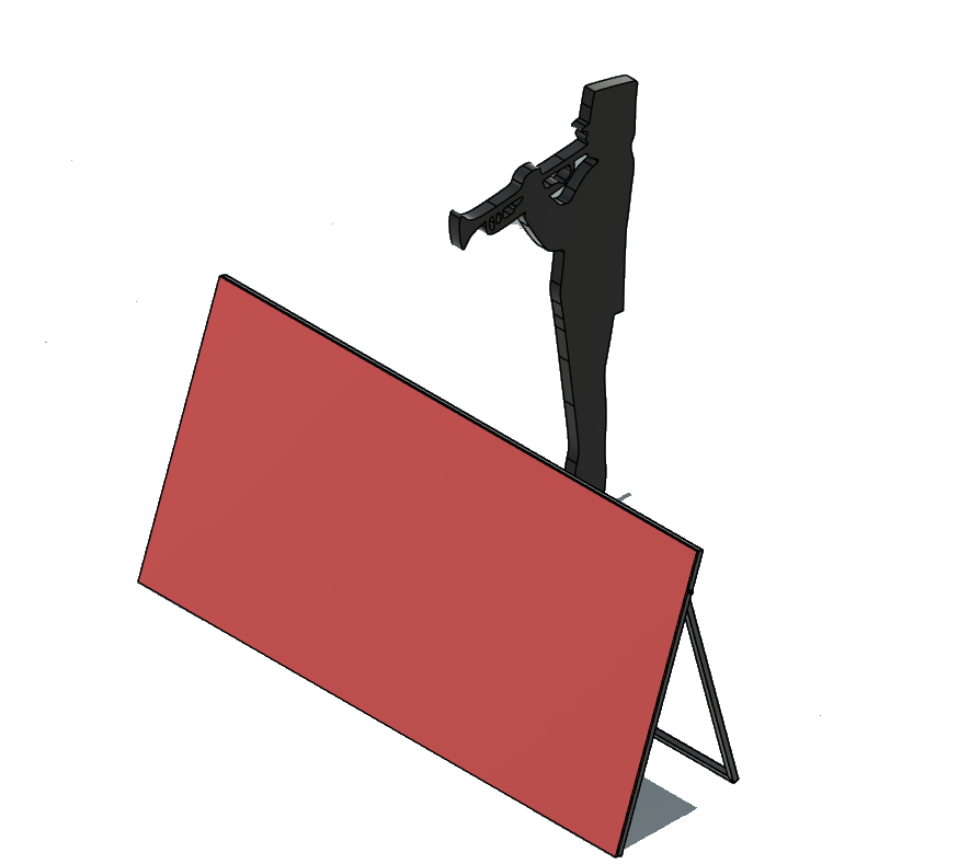
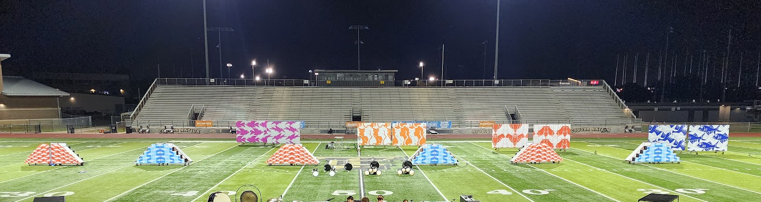
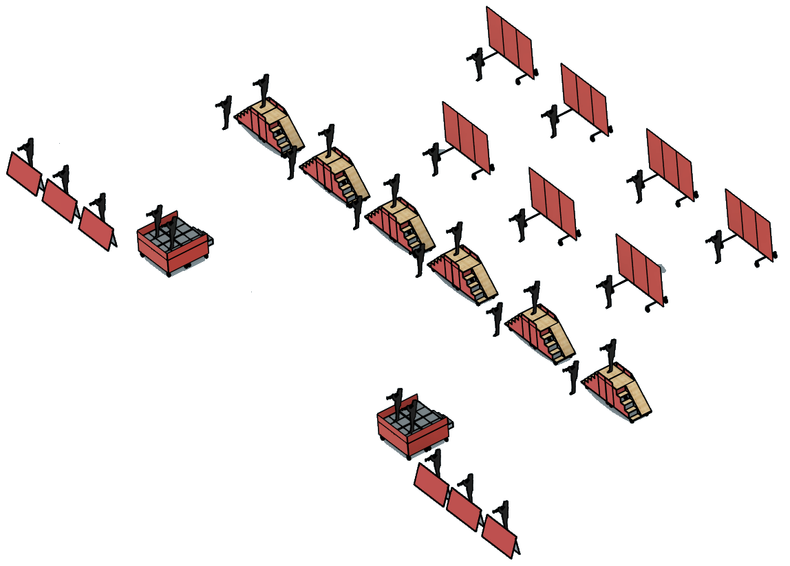
Field layout mockup: seven media frames, twelve stair props, two stages, and ten front screens

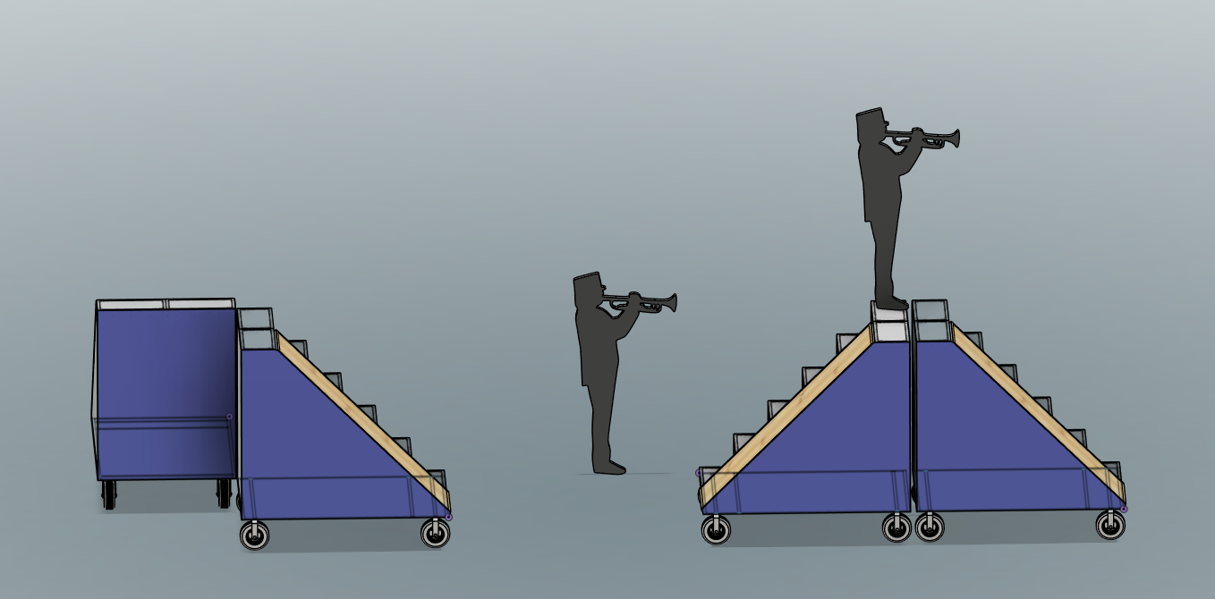
Full field mockup with silhouettes for scale.

With the final prop designs locked in, this is the current plan for what goes on the field:

Item Count Purpose
Stair/slide props 12 Main moving field props
Media frames 7 Backfield visual impact
Stages 2 Featured performers
Front screens 10 Front ensemble visual layer
  • 7 media frames — back screens across the rear of the field.
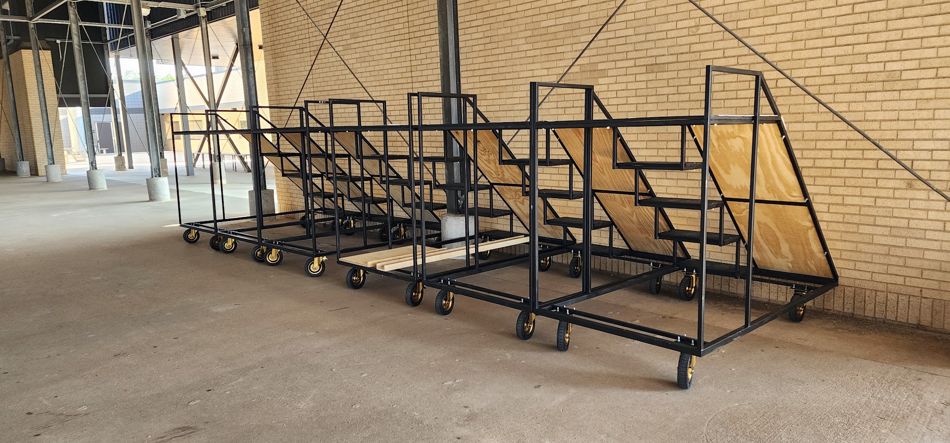
  • 12 stair/slide props — six mirrored pairs staged through the center of the show.
  • 2 stages — elevated platforms for featured performers.
  • 10 front screens — angled panels in the front ensemble area.

Concept & specifications (working)

First prototype targets from design reviews and initial CAD.

CAD render: two props in an L shape with silhouettes for scale

L-shaped arrangement (two units): platforms meeting at 90°.

These were the current targets based on design reviews and the first prototype. Expect changes as we get more real-world feedback.

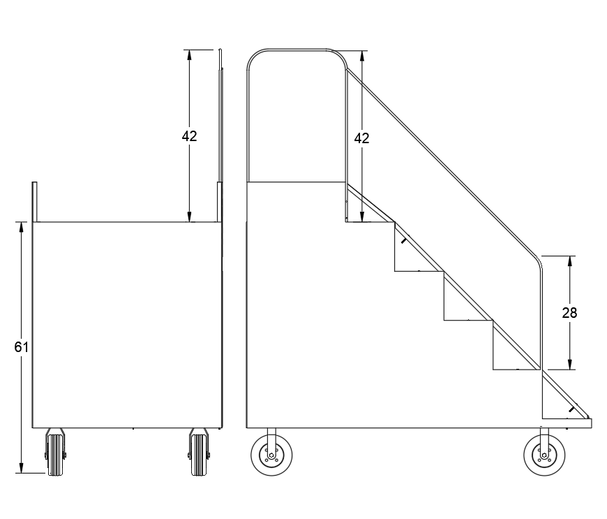
  • Footprint: roughly 7 ft wide by 4 ft deep on casters.
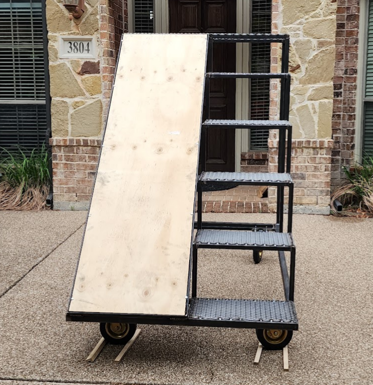
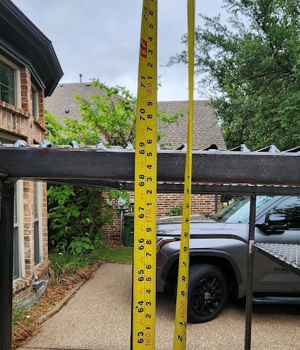
  • Platform height: about 69 in. to the top deck (just under 6 ft depending on wheel height).
  • Stairs: five rises up to the platform; stair width about 2 ft.
  • Top platform: about 2 ft deep, shared between the stair exit and slide entry.
  • Slide: plywood ramp; final surface material and angle will be set after student trials.
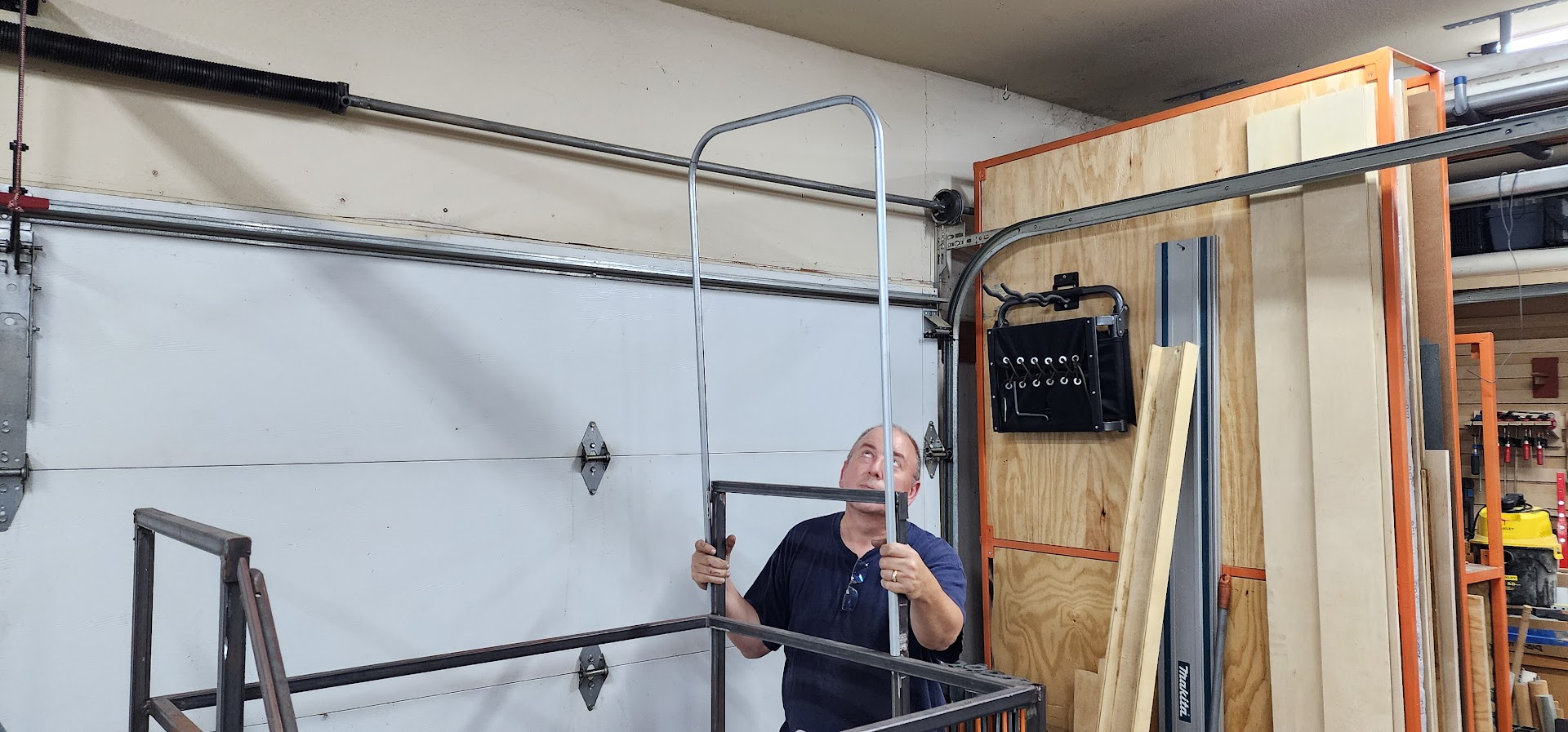
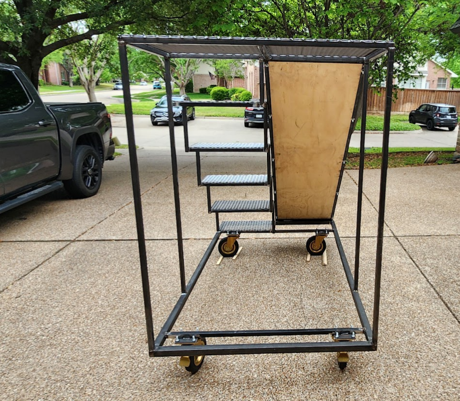
  • Sides: coroplast panels mounted to a steel frame; 1 in. tube handles at about the 4 ft height for maneuvering.
  • Mobility: locking casters at the corners; wheels are inset slightly to avoid interference when props are staged close together.

Budget and total unit count are still being worked with the program. Early estimates have been in the mid–three figures per unit for materials, before final scope is locked in.

Videos

Prototype checks: slide tryout and walkaround.

John testing the slide

Open on YouTube

Prototype overview

Open on YouTube

Design update: version 2

May 2026 — refining the platform after the first prototype trials.

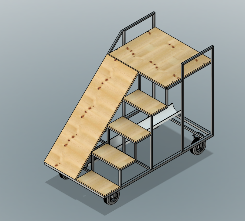
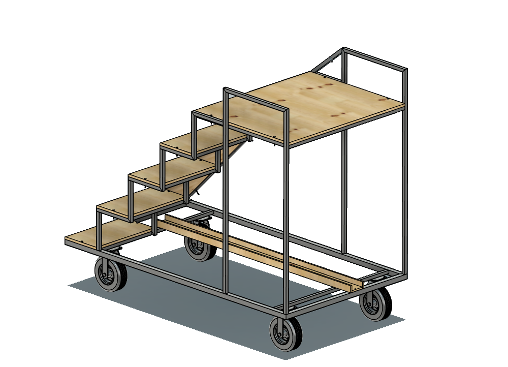
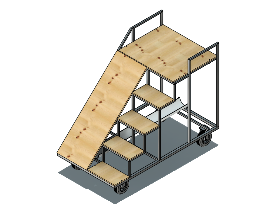
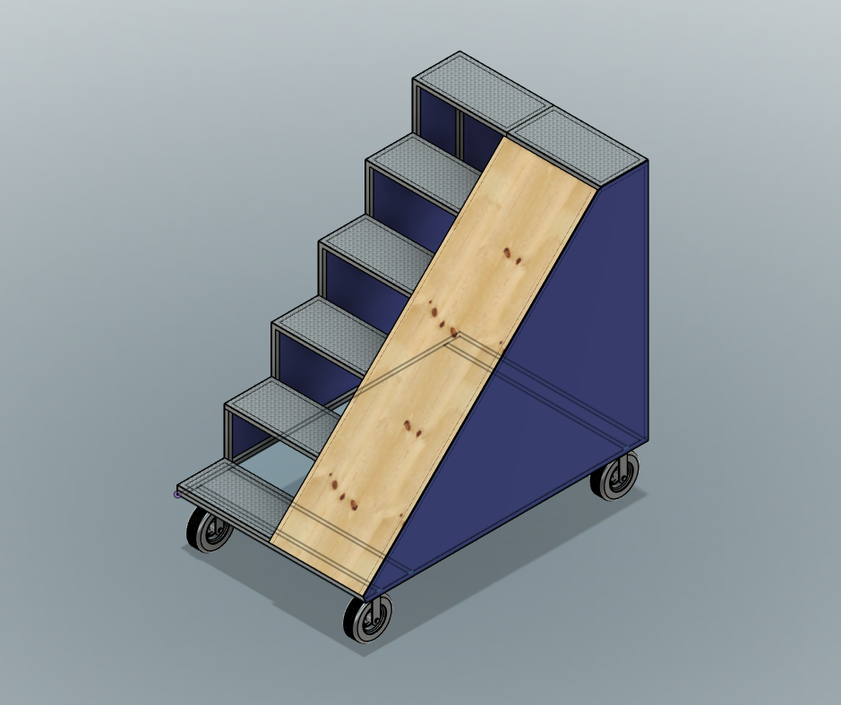
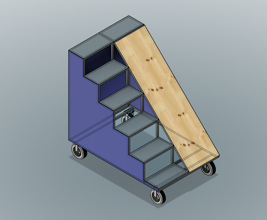
CAD render: version 2 prop with larger top platform
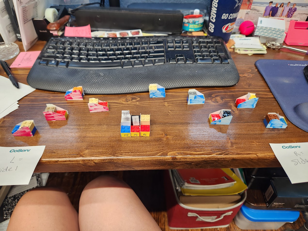
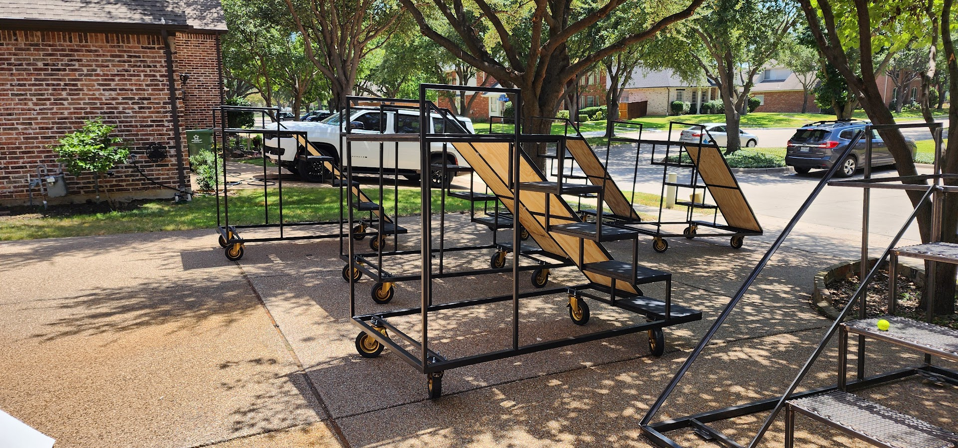
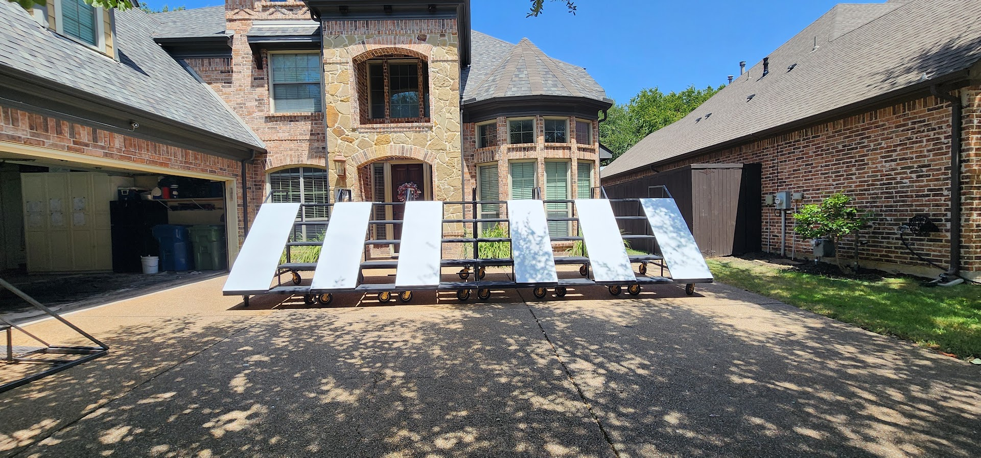
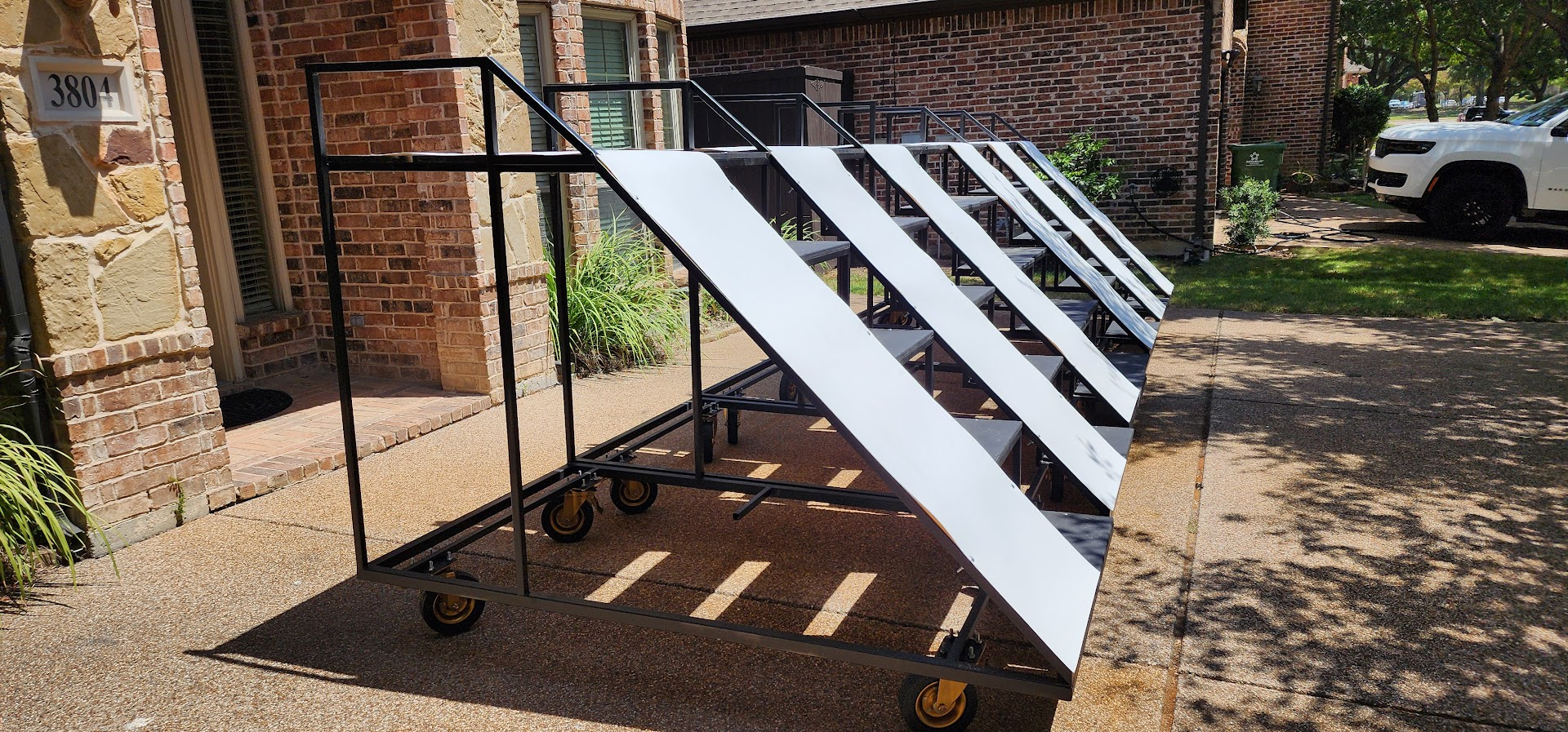
version 2 coroplast mockup, view 1
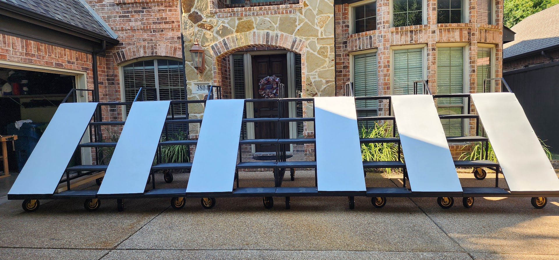
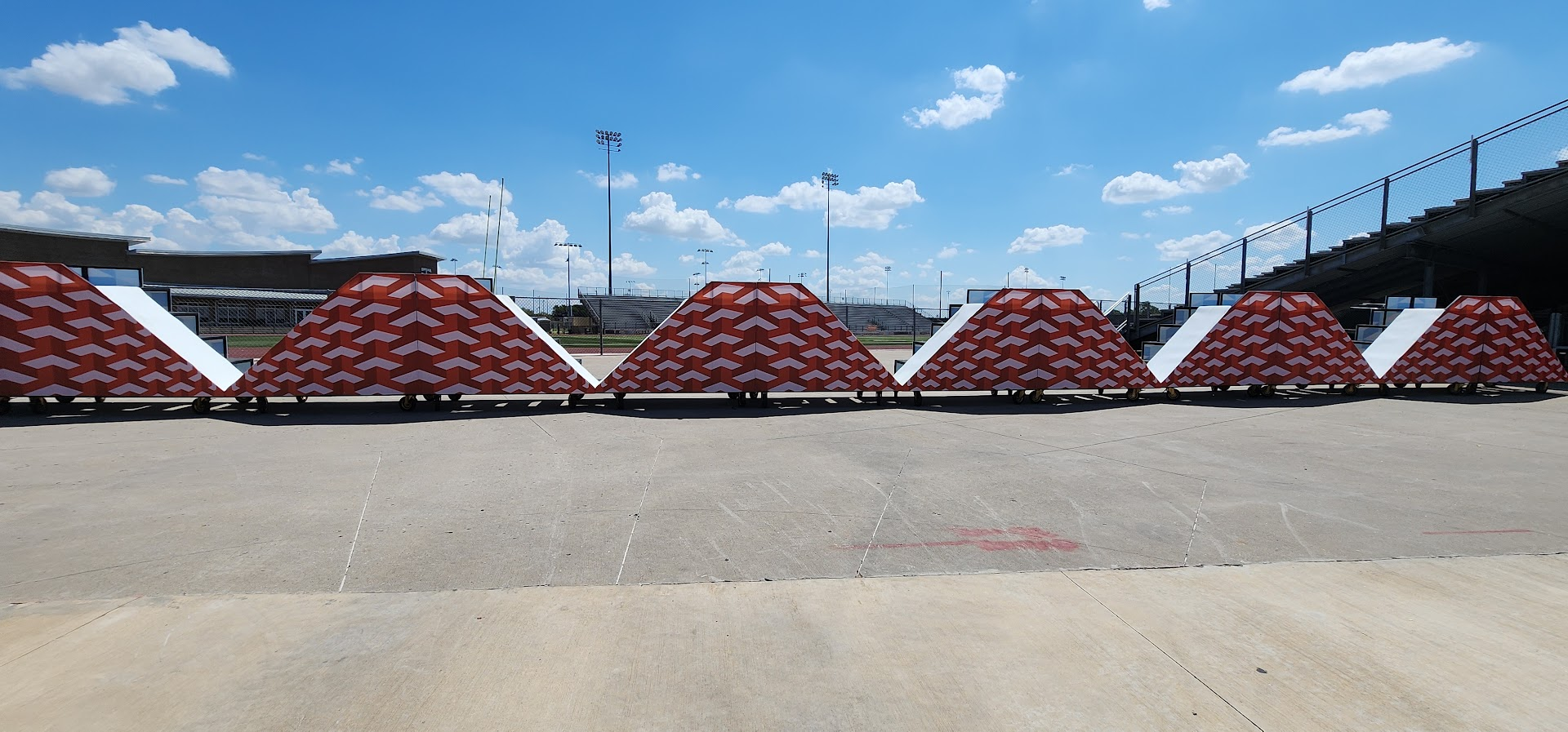
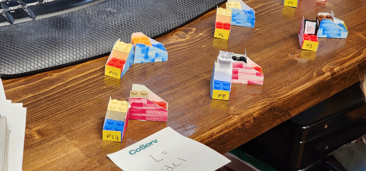
version 2 coroplast mockup, view 2
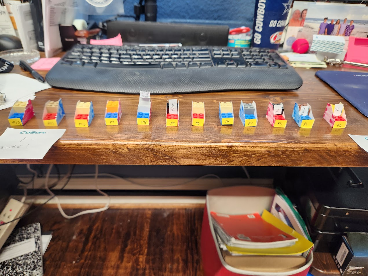
version 2 coroplast mockup, view 3
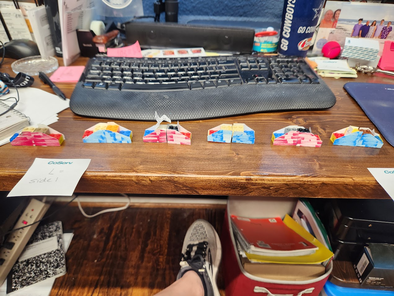
version 2 coroplast mockup, view 4
version 2 coroplast mockup, view 5
version 2 prototype, view 6
version 2 prototype, view 7
version 2 prototype, view 8

Version 2 prototype

Open on YouTube

The thought is that increasing the size of the top platform and lowering it by one step would make it more stable and easier for the students to stand on and transition onto the slide.

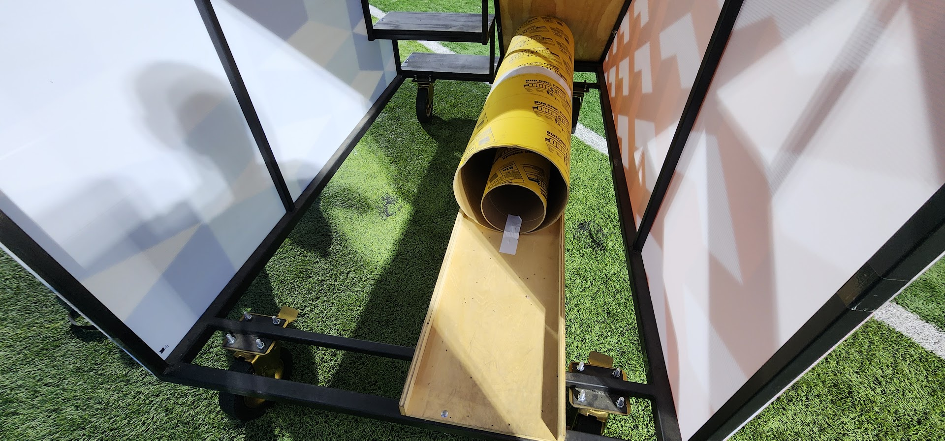
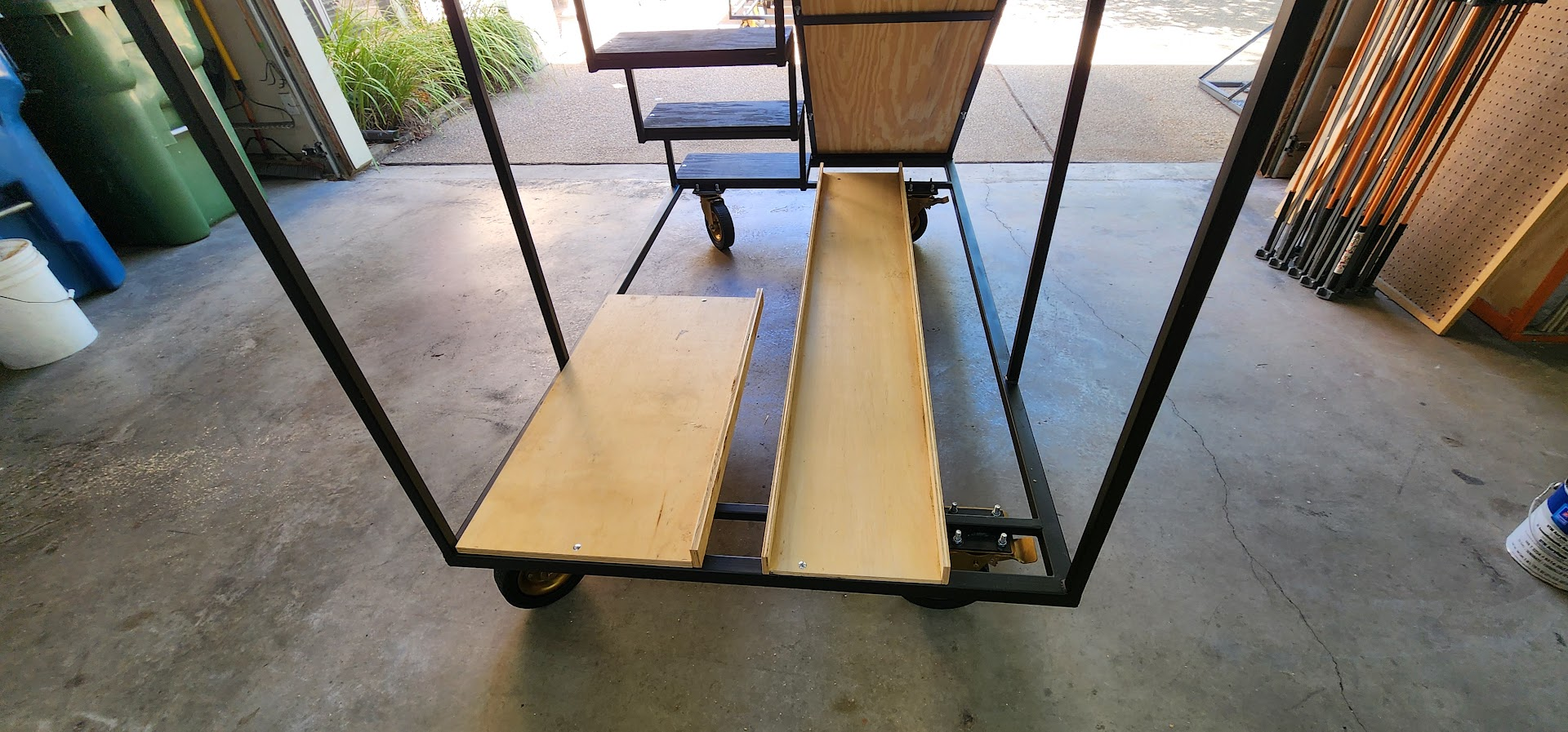
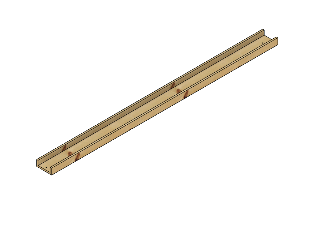
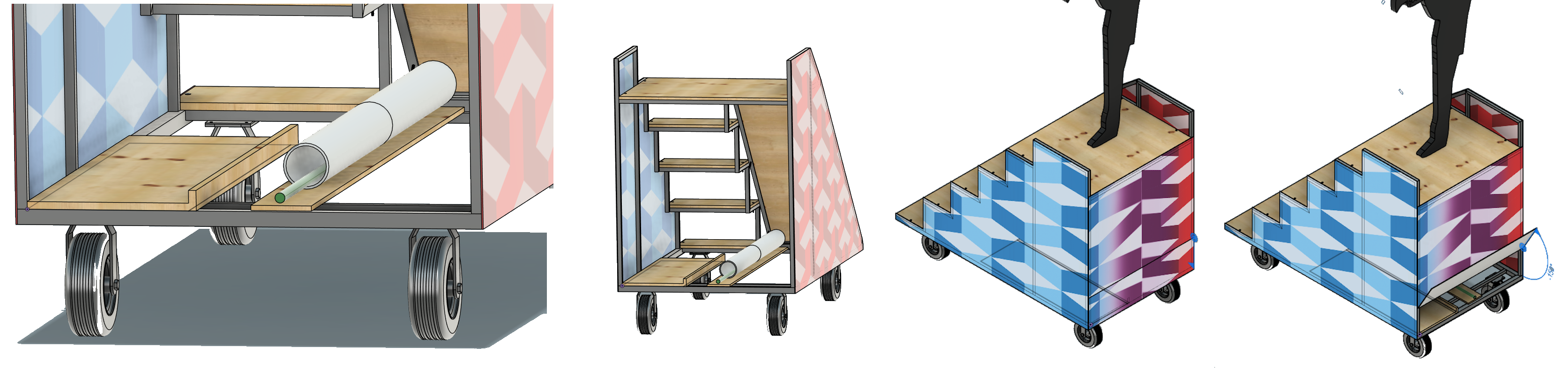
This newer version has the top platform at 4 × 3 ft without increasing the overall length of the prop, so it will still fit in the box trucks. It still has the sides extending upward to act as handles, and keeps the same side profile for coroplast. The angle of the slide is the same. I have also modeled a flag trough in the bottom.

I plan to modify the current prop’s top platform to match it and bring the prop to Audition Camp so the students can test it again. Hopefully, that will finalize the design so we can start building in June.

  • Footprint: roughly 7 ft wide by 4 ft deep on casters (unchanged overall length for box-truck loading).
  • Stairs: four rises to the platform (one fewer than the first prototype); stair width about 2 ft.
  • Top platform: 4 × 3 ft, shared between the stair exit and slide entry.
  • Slide: same ramp angle as the prototype; surface material still to be confirmed after student trials.
  • Sides: coroplast panels on the same side profile; vertical extensions act as handles (~4 ft high, 1 in. tube).
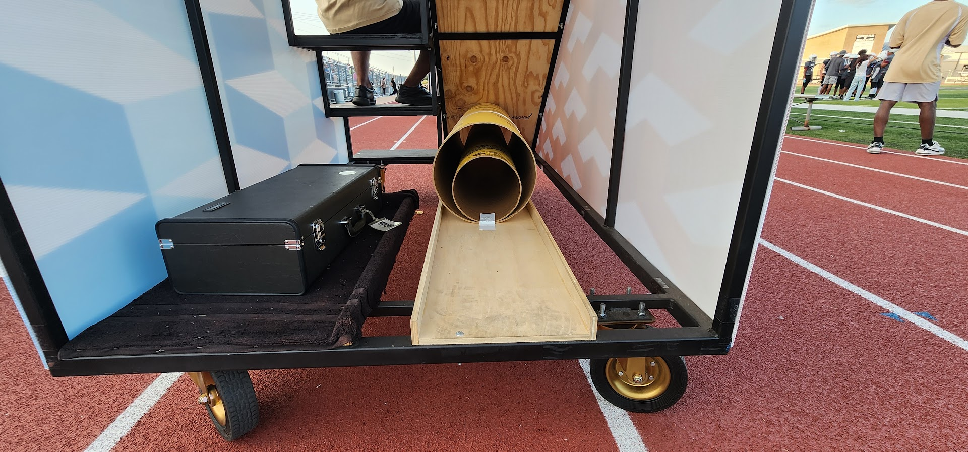
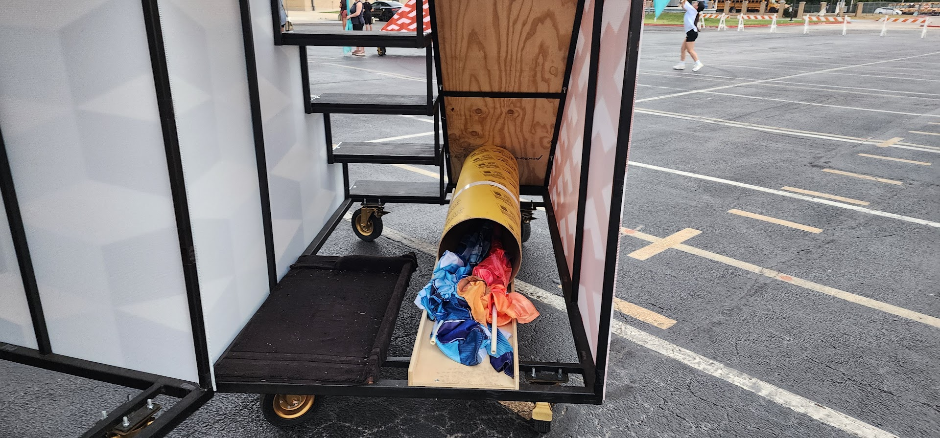
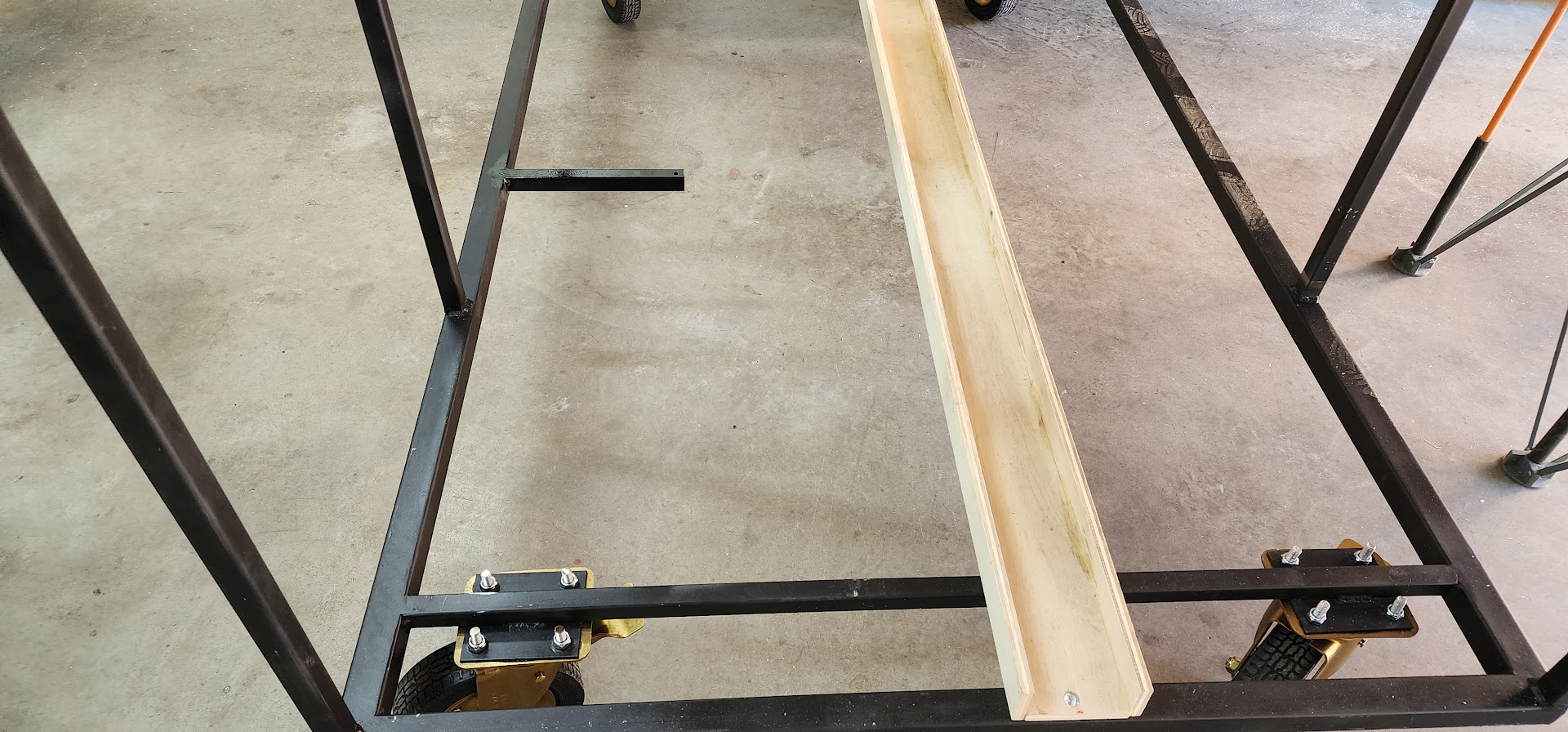
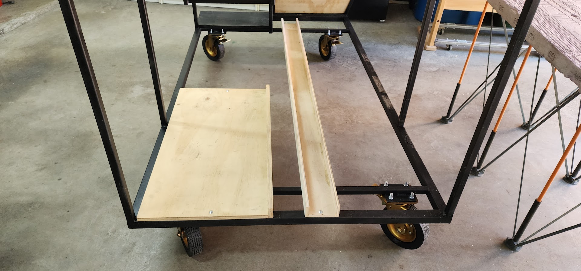
  • Flag trough: modeled in the bottom of the frame for pole storage.
  • Mobility: locking casters at the corners; wheels inset slightly when props are staged close together.

Coroplast: sheets & layouts

June 2026 — final CAD sheet layouts for the build phase.

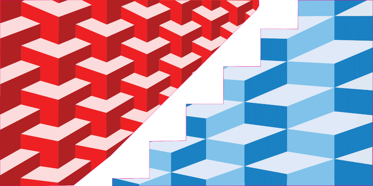
Now that we have a final design for the props, the CAD drawings are complete and we are moving into the build phase. Based on those drawings, I have mapped out coroplast sheet layouts to optimize material usage and minimize cost.

We will order sheets uncut and cut them ourselves. Please include bleed along the cut lines to allow tolerance during cutting and to account for minor variations in prop dimensions during assembly.

Stair/slide props

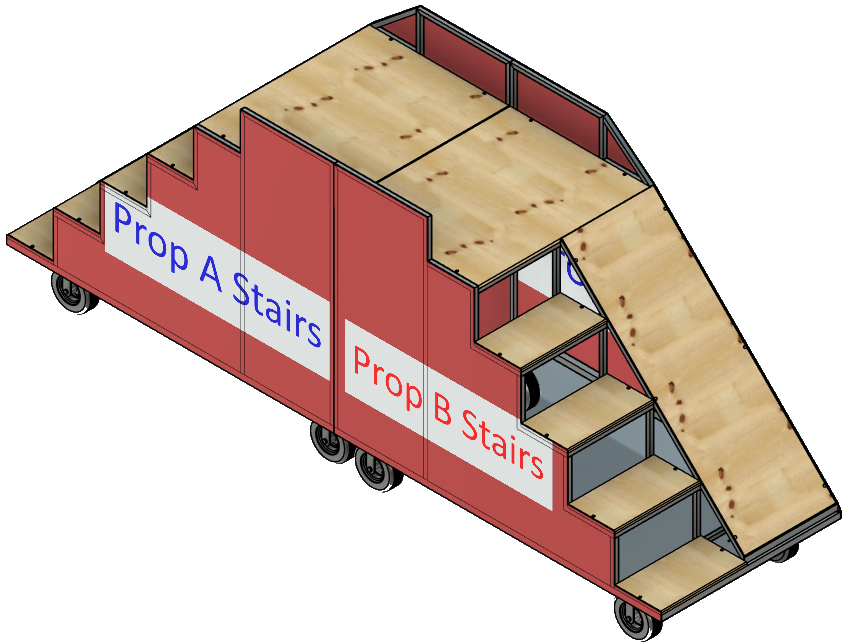
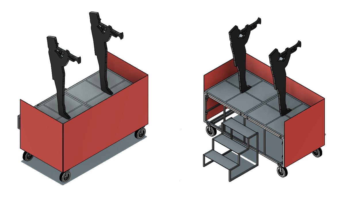
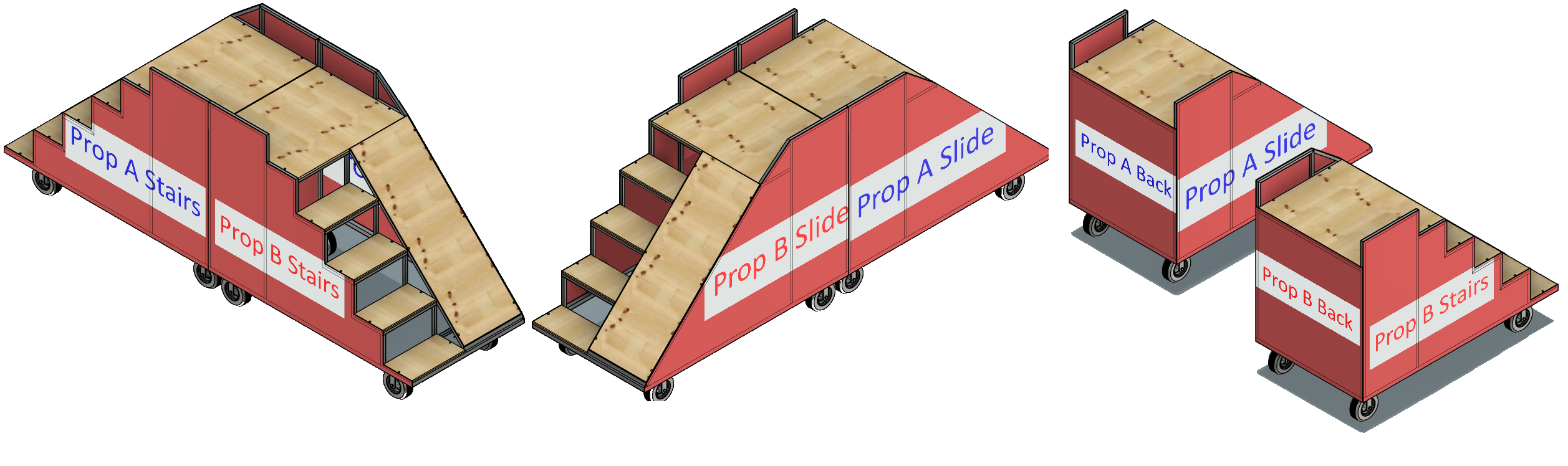
CAD mockup: mirrored stair pair with coroplast side panels labeled Prop A and Prop B

Mirrored stair pair — one of six on the field.

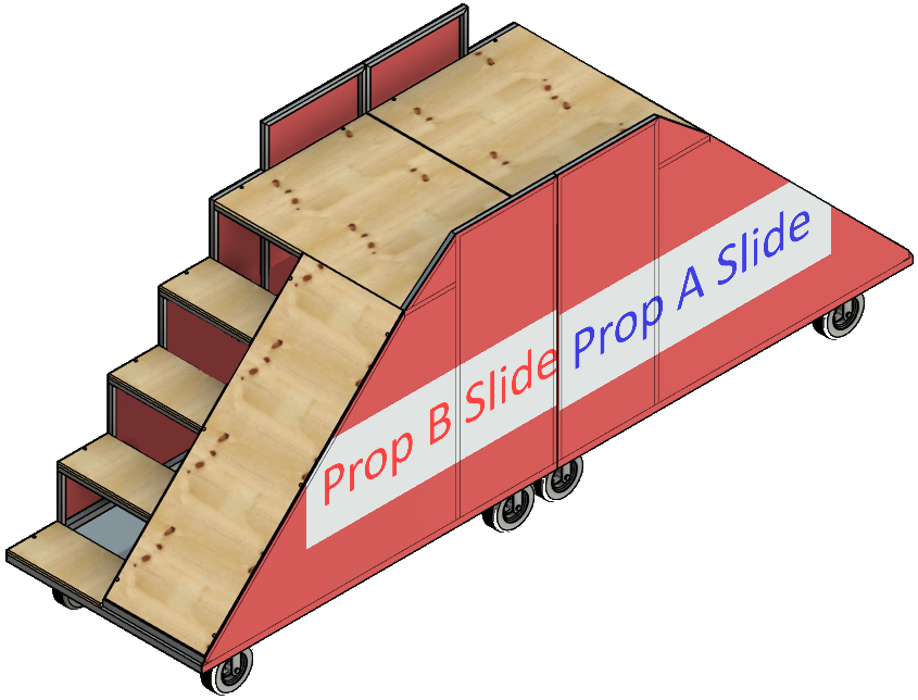
CAD mockup: mirrored slide pair with coroplast side panels

Mirrored slide pair — sides follow the stair/slide profile.

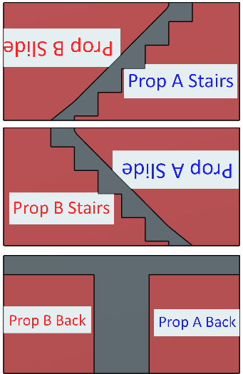
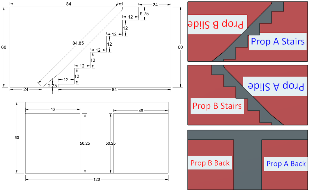
There are six mirrored pairs of stair/slide props (twelve units total). For each pair, all four side panels can be produced from three 5 × 10 ft sheets of 4 mm coroplast.

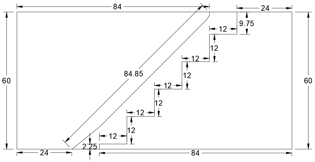
The artwork layout must follow the pattern below so we obtain the four required side panels while still printing on only one side of the coroplast. Each piece is labeled so the graphics artist knows how to position it on the sheet. Several pieces must be rotated to maximize material efficiency and ensure the artwork appears correctly once installed — note the text-orientation callouts on the layout drawing.

Total: 6 pairs × 3 sheets = 18 sheets of 5 × 10 ft, 4 mm coroplast.

Coroplast sheet layout for one mirrored pair: three 5 by 10 foot sheets with labeled cut pieces for Prop A and Prop B

Sheet layout for one mirrored pair — blue labels are Prop A, red labels are Prop B. Upside-down text is intentional for correct artwork orientation after installation.

Cut measurements for stair and slide side panels on a 9 by 5 foot sheet section

Stair/slide side panel cut dimensions (sheet 1).

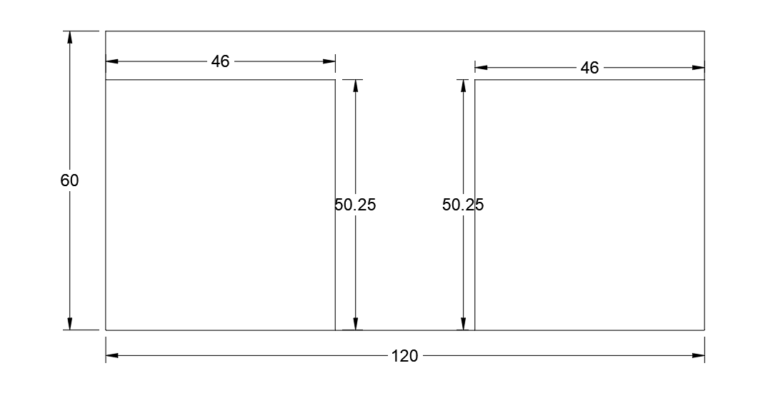
Cut measurements for back panels on a 10 by 5 foot sheet

Back panel cut dimensions (sheet 3).

Stages

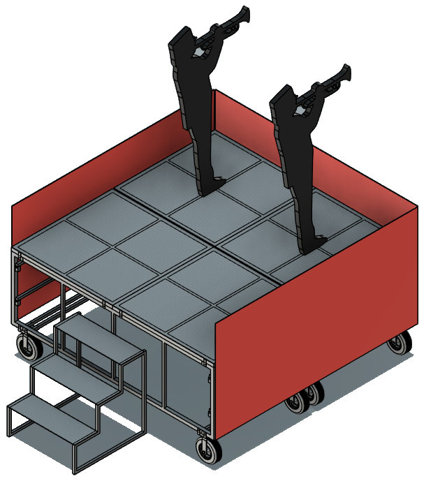
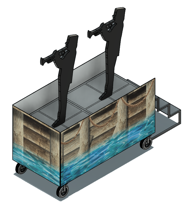
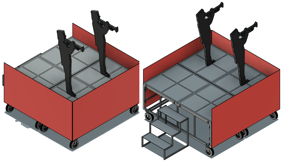
CAD mockup: stage with coroplast on three sides
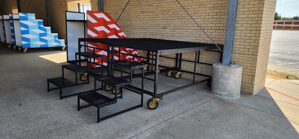
CAD mockup: three-step stairs for stage access

For the two stages, the plan is to cover three sides with coroplast, using 4 × 8 ft sheets of 4 mm coroplast — three sheets per stage, six sheets total.

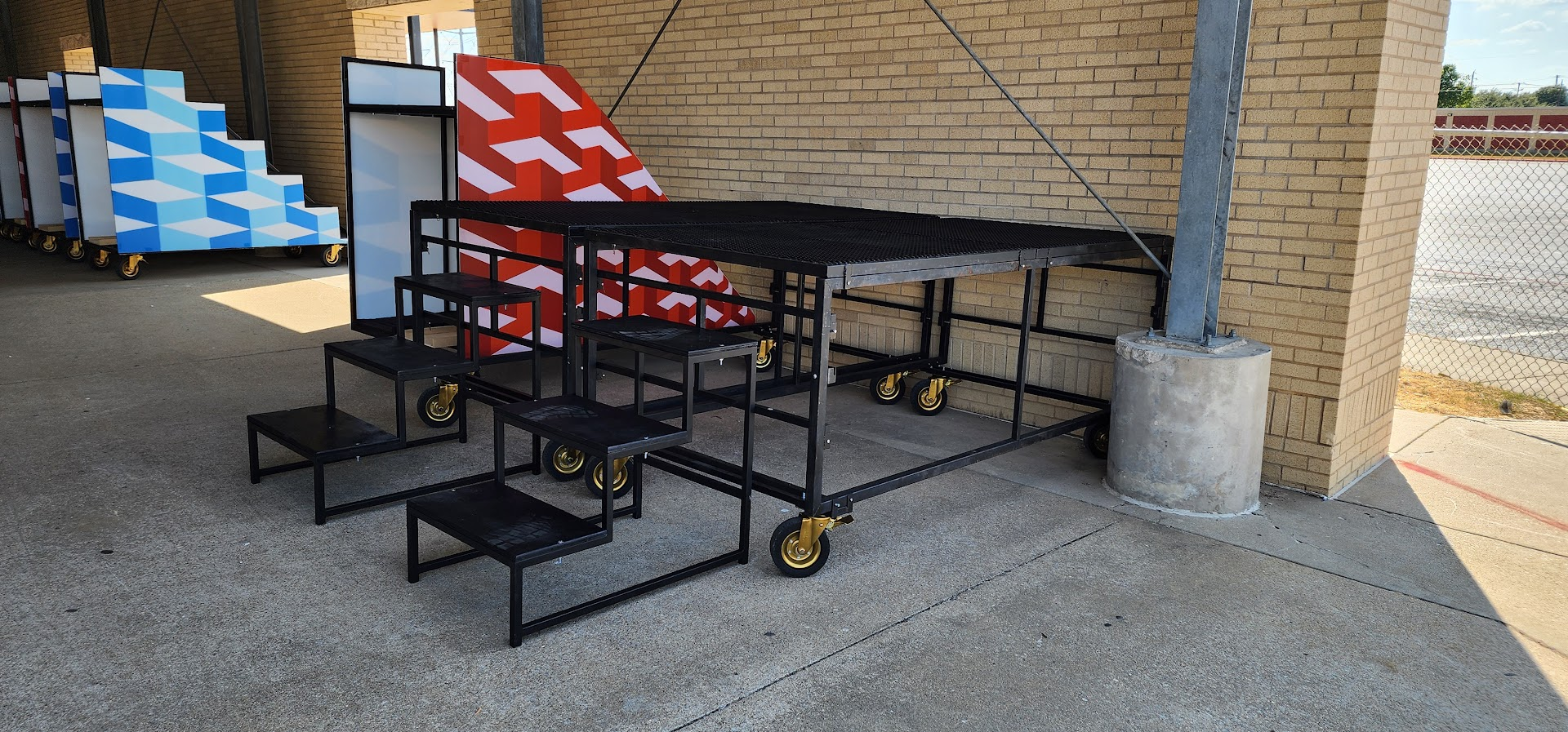
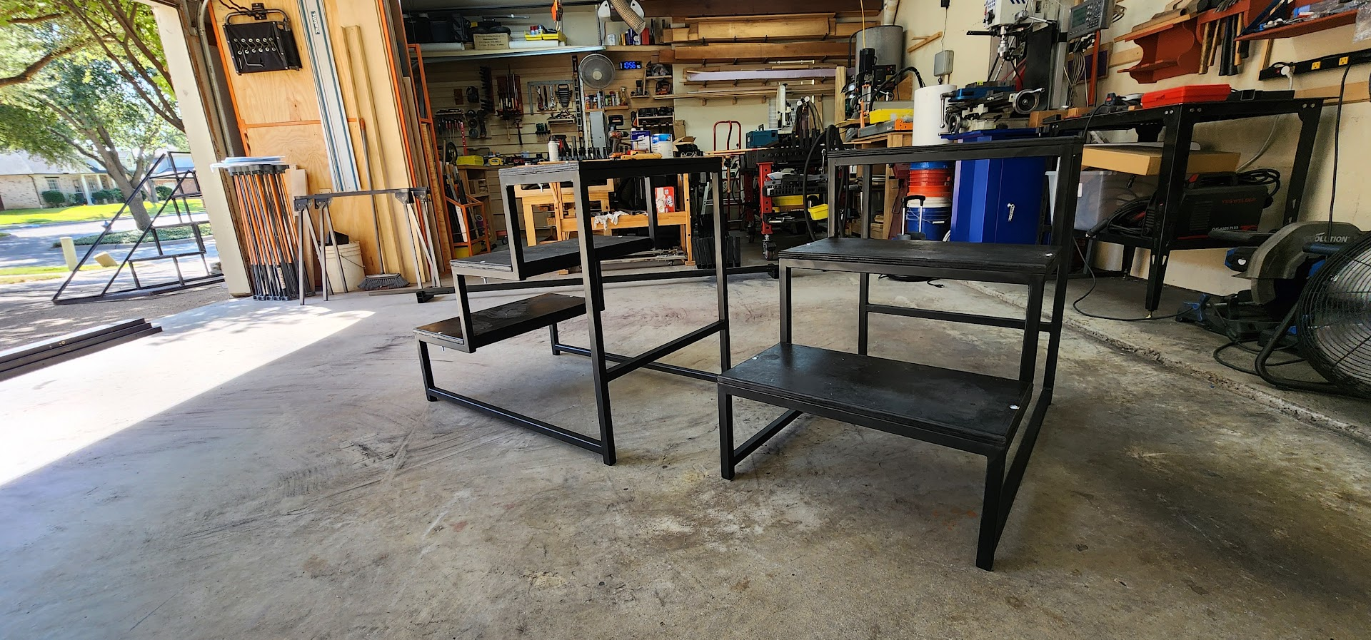
I have also mocked up a three-step stair set for getting on and off the stage. That should meet our access needs for performers.

Media frames (backdrops)

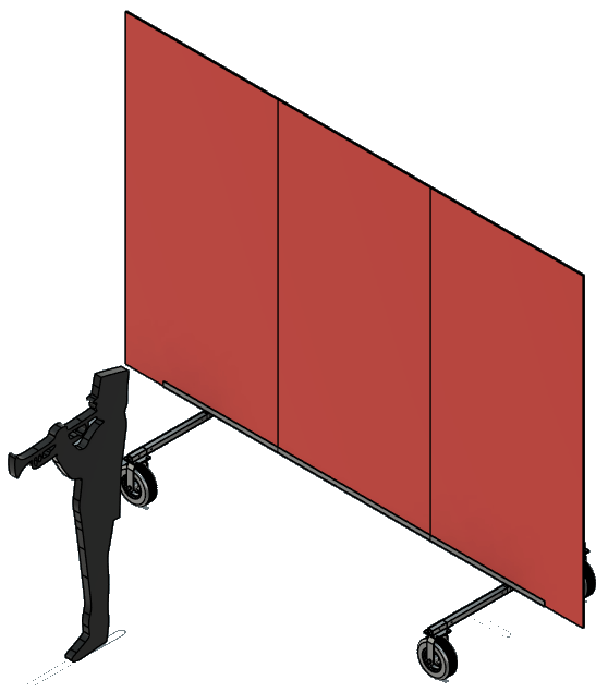
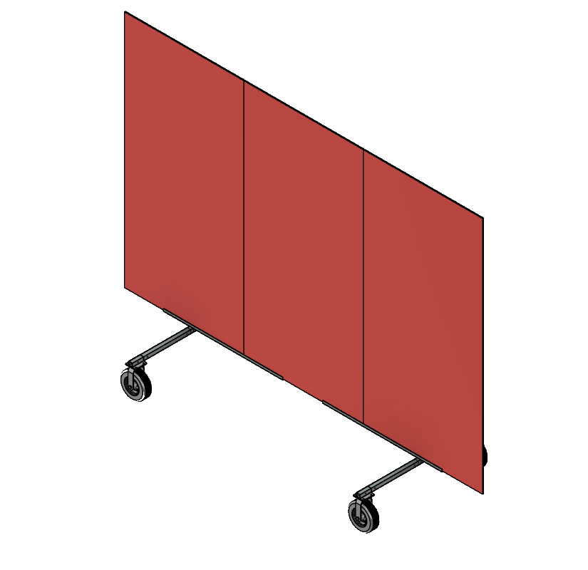
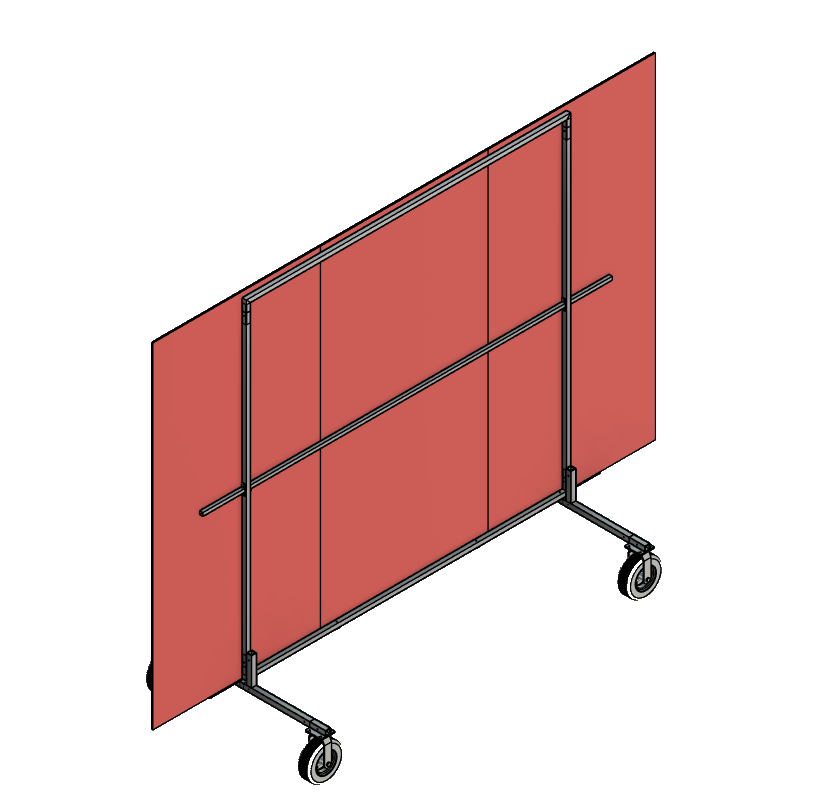
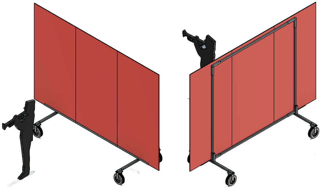
CAD mockup: media frame with three vertical coroplast panels
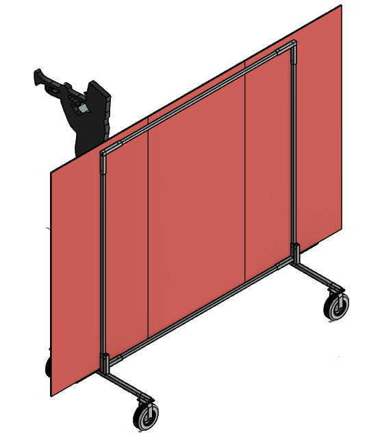
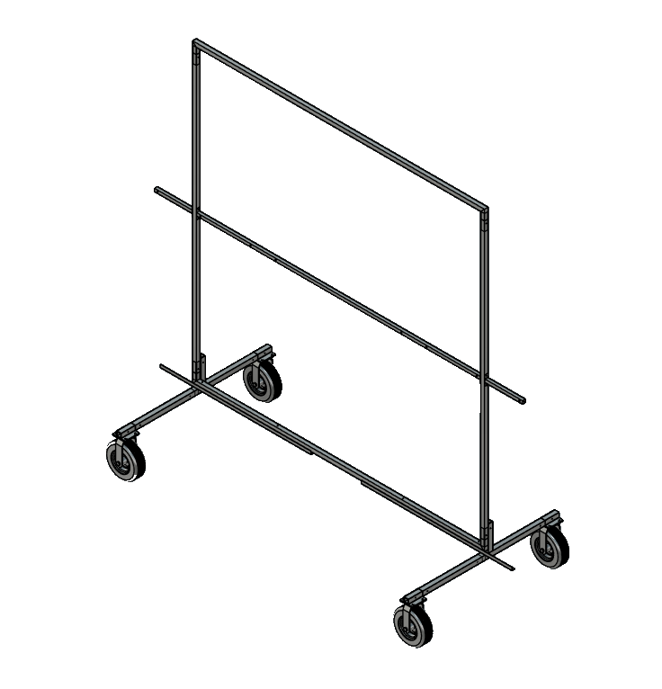
CAD mockup: media frame rear view showing frame structure

For the seven back media frames, the design stays at no more than three 4 × 8 ft sheets of 10 mm coroplast per frame — 21 sheets total. The mockups show how three sheets fit on each frame.

Front screens

CAD mockup: angled front screen with one coroplast panel

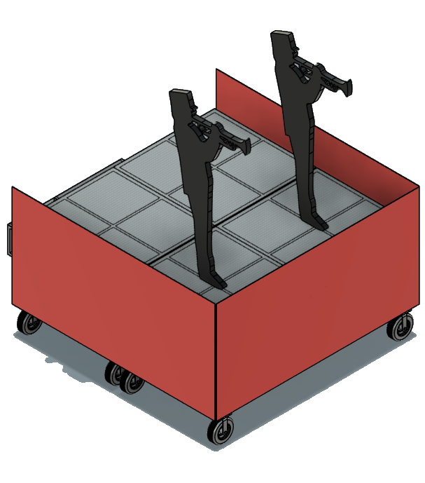
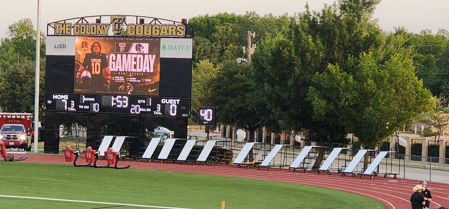
The current field mockup shows six; the latest discussion was to have 10 screens. Each screen takes one 4 × 8 ft sheet of 4 mm coroplast.

Coroplast order summary

  • 18 sheets — 5 × 10 ft, 4 mm (stair/slide props)
  • 6 sheets — 4 × 8 ft, 4 mm (stages)
  • 21 sheets — 4 × 8 ft, 10 mm (media frames)
  • 10 sheets — 4 × 8 ft, 4 mm (front screens)

Backdrops: Media Frames & 10 mm Coroplast

We’re going back to the media-frame approach with 10 mm coroplast for the backdrops. This is my third pass at solving how to attach panels cleanly without relying on Velcro.

I’ve never liked Velcro for this use. It behaves more like tape than a structural solution and doesn’t hold up well to the repeated assembly and disassembly that happens throughout the season. We leaned heavily on Velcro for the 2021 season props and ended up replacing it after nearly every contest, which is something I want to avoid repeating.

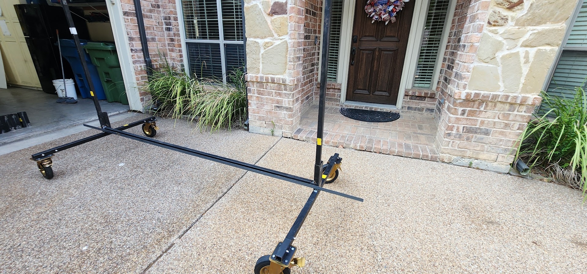
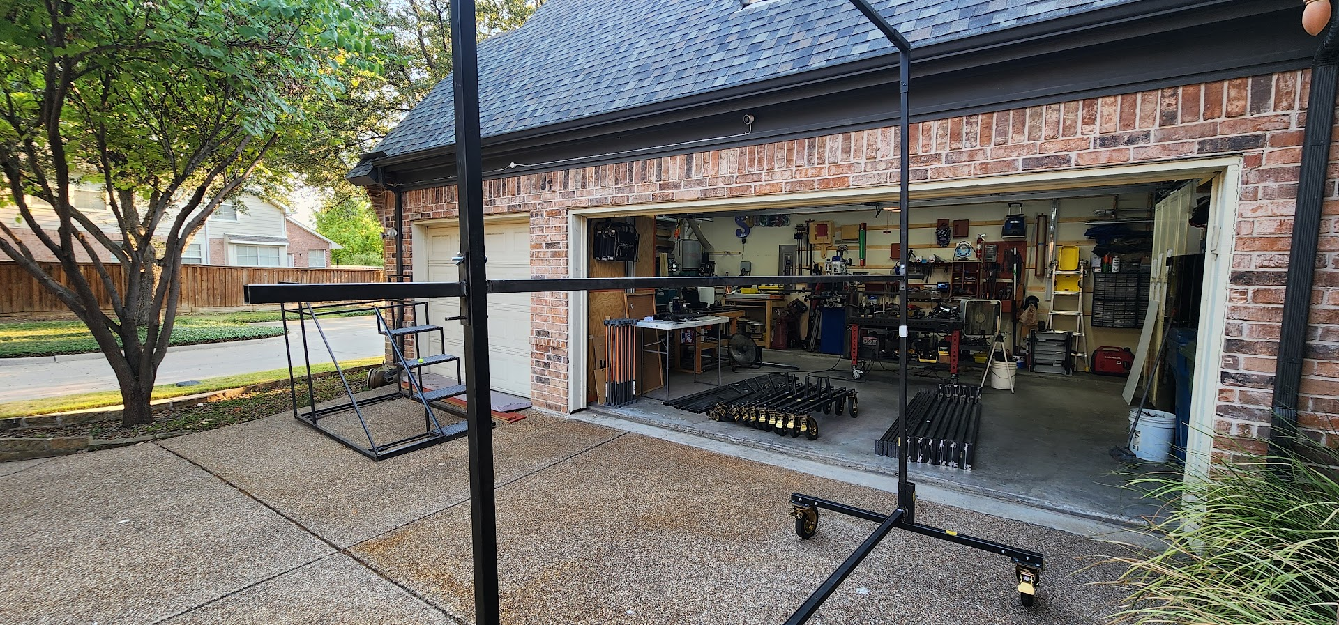
This year I’m planning to add angle iron along the bottom of the frame to create a channel for the coroplast to sit in. That should be more stable than last year’s bottom-bolt approach.

I also want to add a mid-frame rail to give us a solid attachment point across the center. Attaching only at the edges left the panels unsupported, which led to alignment issues and gaps at the seams.

I may still use a small strip of Velcro at the top rail to control the top edge, but only if the rest of the structure is doing the real work.

Trailer: Racks, Frames, and Coroplast Storage

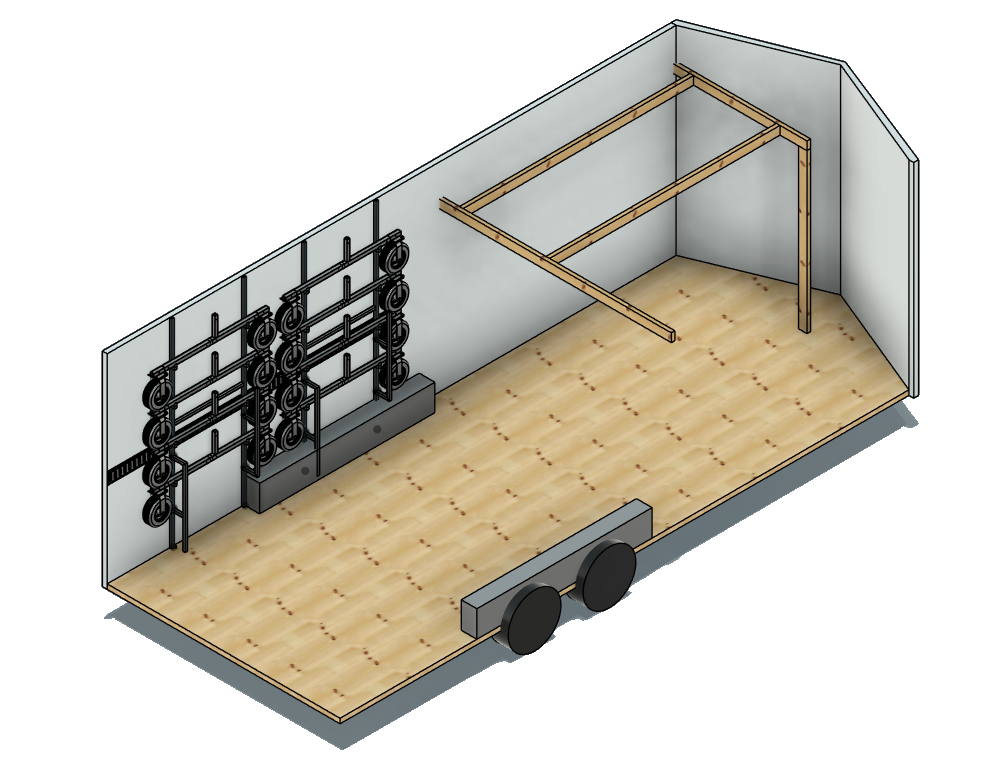
Bringing the backdrops back means another pass at how everything rides in the trailer. Last year was functional, but not efficient.

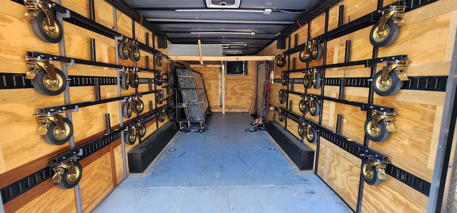
This year I plan to build a dedicated rack system so each component has a defined place instead of competing for floor space.

Since this is also my final year as props lead, and assuming the media-frame props will stick around, it makes sense to build a repeatable storage solution inside the 20 ft trailer that will continue to be useful after I’m done.

I also want to improve the coroplast storage by adding a better way to secure sheets to a shelf or wall. The goal is to keep them flat and avoid warping during transport.

Front Stages

We’re reusing and expanding last season’s front stages. The plan is to add one additional 4 × 8 ft section, bringing the total to four, and then stage them in pairs on each side of the front ensemble.

I also plan to build two simple sets of steps that sit on the ground behind the stages to make getting on and off easier. For transport, the steps will ride on top of the stages so they don’t take up additional trailer space.

Load planning: trucks & trailer

Packing layout for travel to contests.

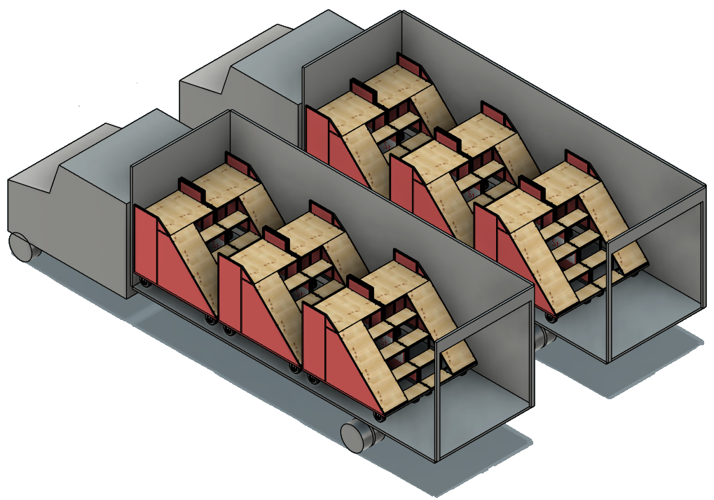
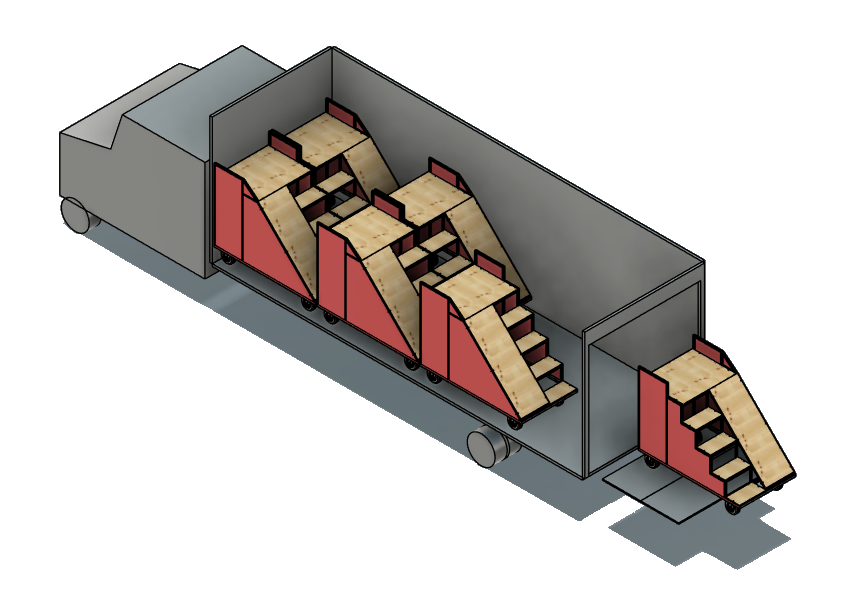
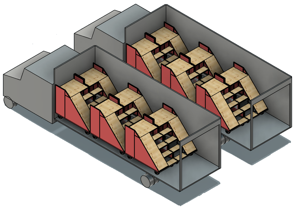
CAD mockup: two 26-foot box trucks each loaded with six stair props

Two 26 ft box trucks — six stair props per truck.

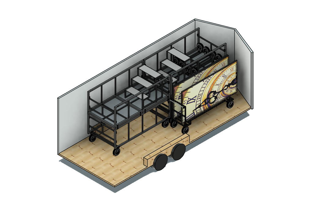
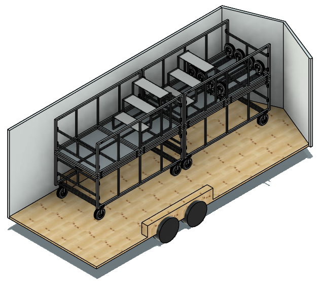
CAD mockup: 20-foot trailer interior with stage props stacked two-high

20 ft trailer — stage props stacked two-high.

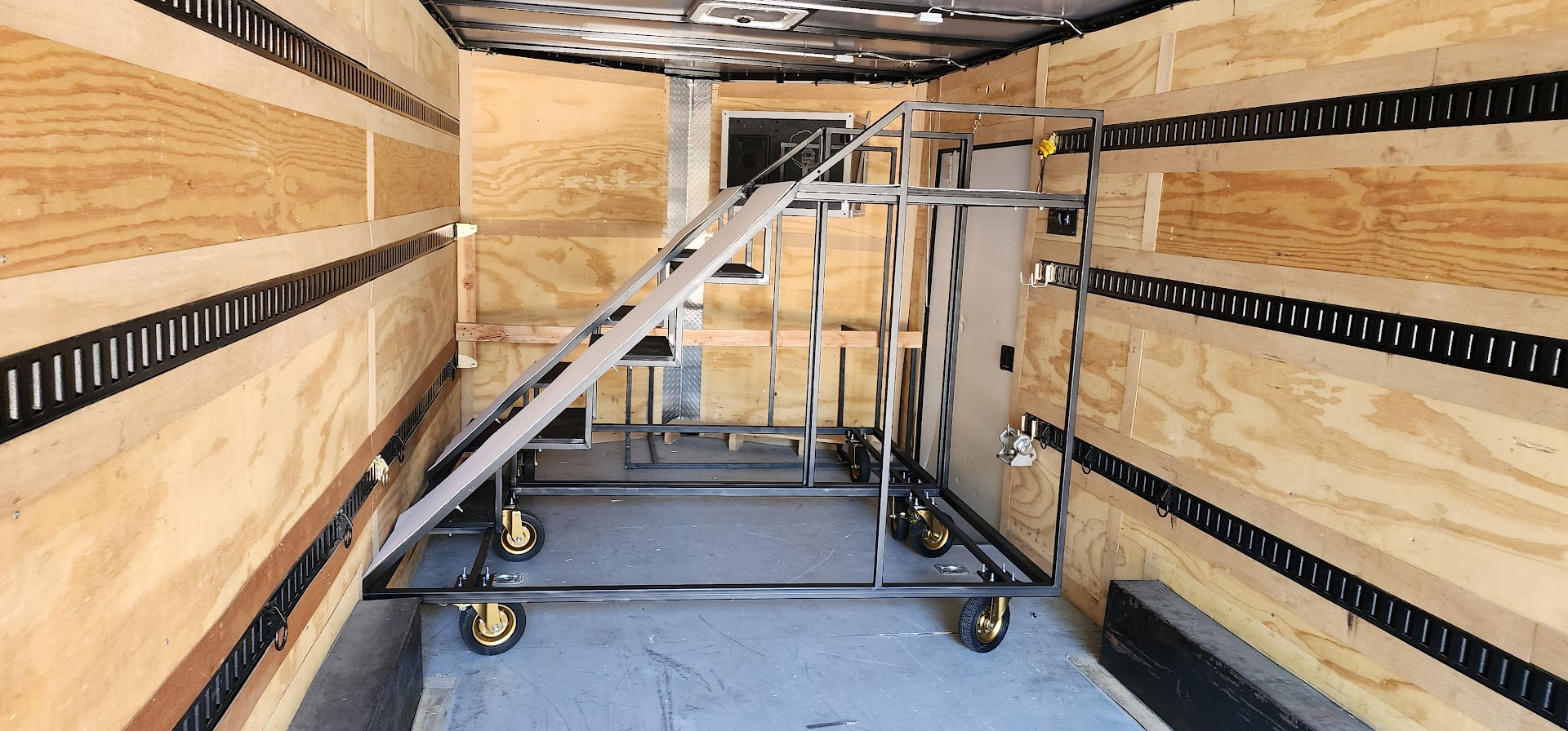
I have mocked up how six stair props fit in each 26 ft box truck — all twelve units across the two box trucks. The prop dimensions were deliberately constrained during design so they fit without disassembly.

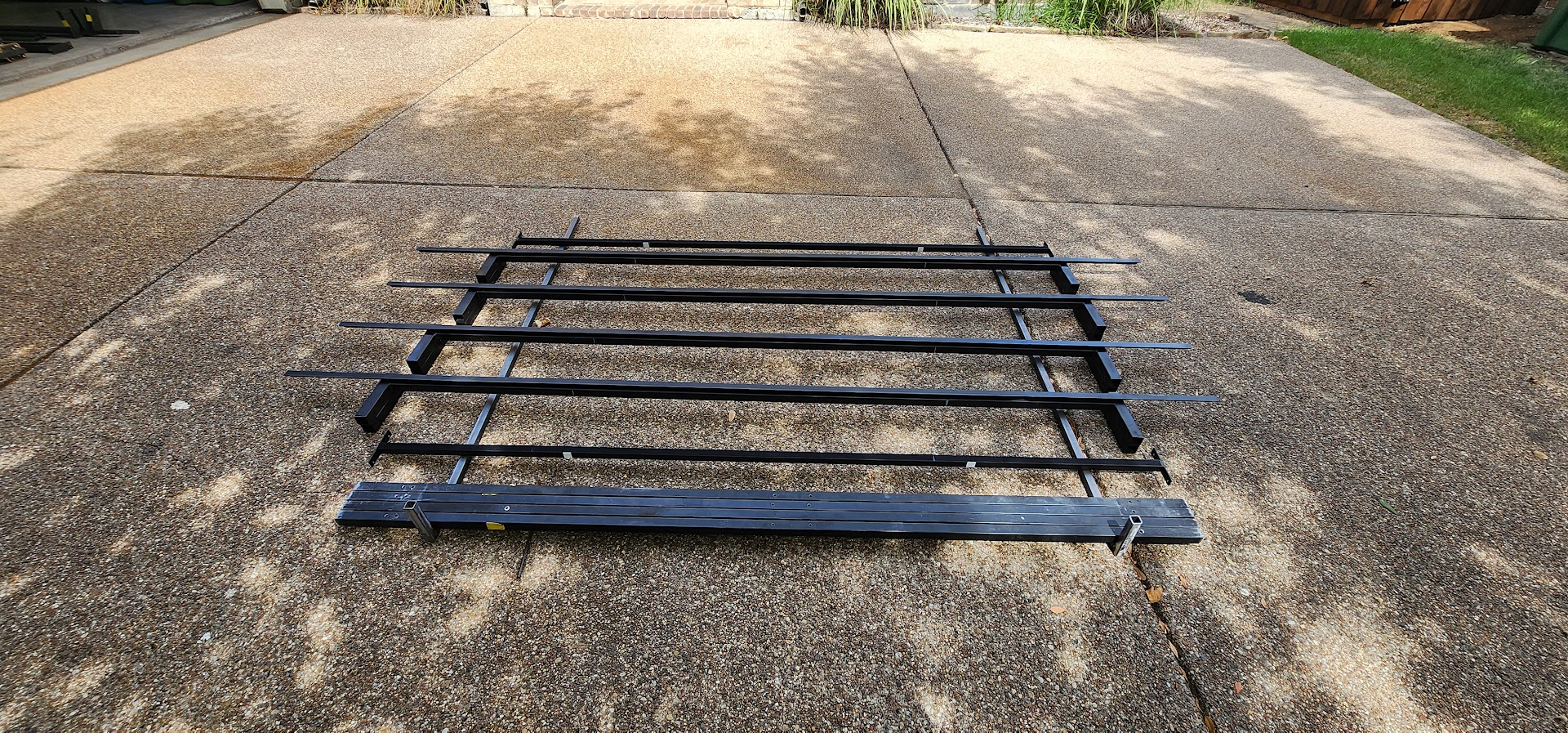
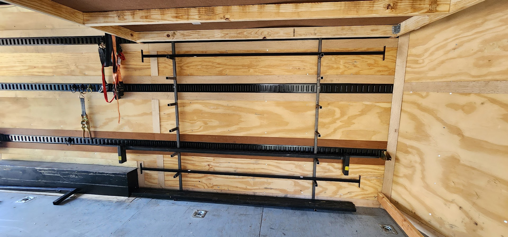
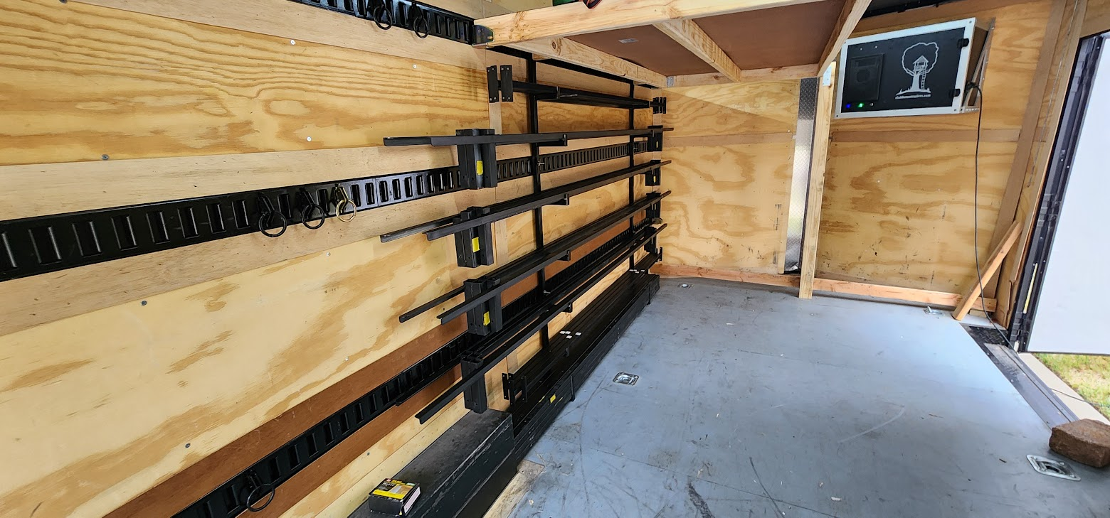
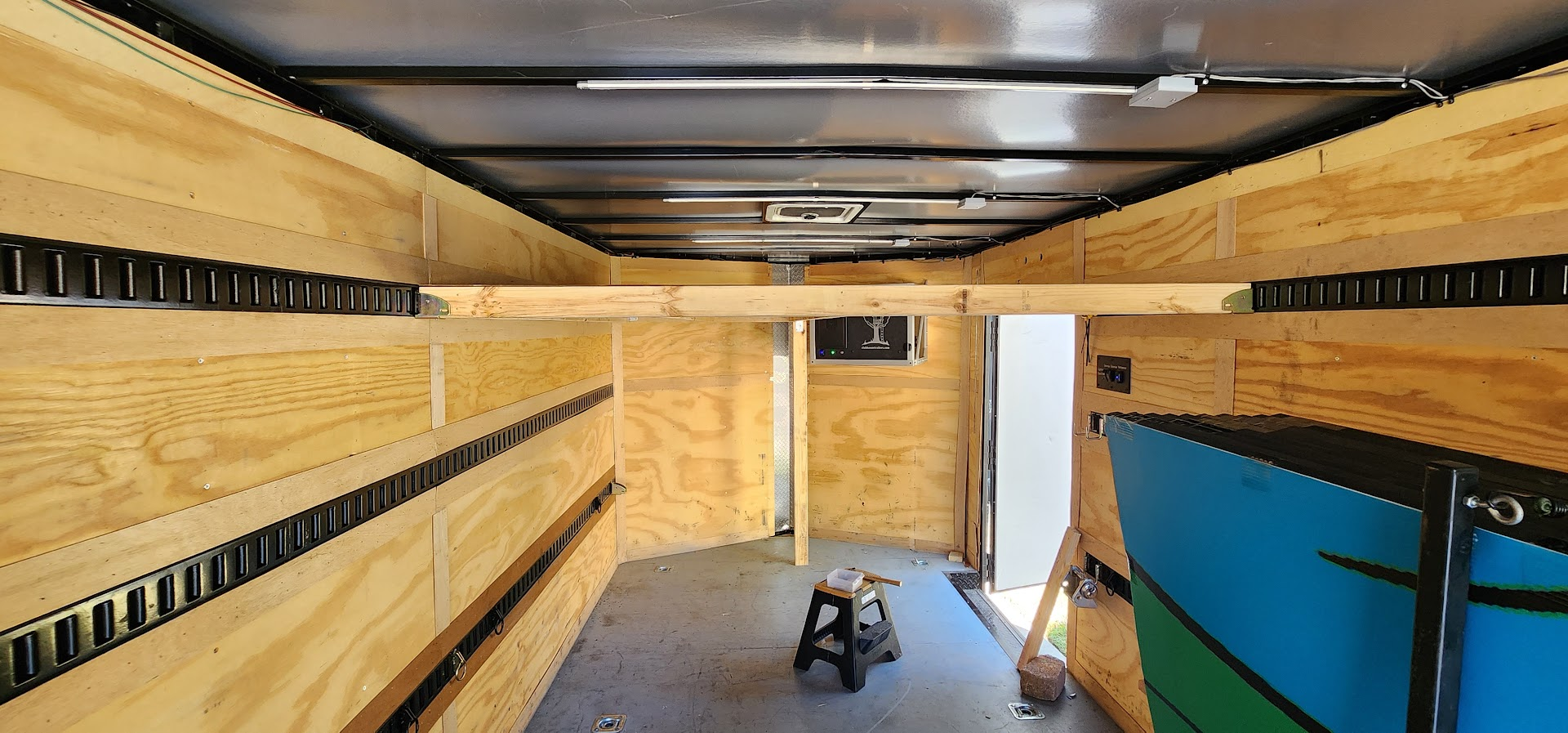
In the 20 ft trailer, stage props can be stacked two-high along the wall; coroplast will be stored in a rack against the wall, and media frames will be stored on the opposite wall.

I also plan to work on something to help with loading props onto the truck lift gate, so no one has to hold the end of a prop that hangs off the gate during loading.

CAD mockup: stair prop on box truck liftgate with the rear end hanging off the platform

A prop on the liftgate — the stair end hangs off the platform and needs support during loading.

Media frames with coroplast, front stages, front-screen carts, and other overflow still need to be mapped across the box trucks and the 20 ft trailer. The goal is to know exactly how much space we have and how much room remains in the box trucks for overflow electronics that would otherwise go on the semi.

Ideally, we remove as much guesswork as possible from contest weekends and make load-in predictable.

All told, this is shaping up to be a big props year, both in size and in complexity. As my final season as props lead, I want this page to be a useful record — not just of what we built, but of the decisions that got us there.

Timeline

Key milestones from the Progress Blog (newest first).

days

Project underway

Since February 17, 2026 — Props Kickoff

days

Full production

Since June 12, 2026 — Metal Has Arrived

  • June 19, 2026 –

    Welding production — steps, platform tops, platform legs, and wheel plate sub-assemblies; 84-inch pieces drilled and assembled; evening fabrication sessions continue.

  • June 13–17, 2026

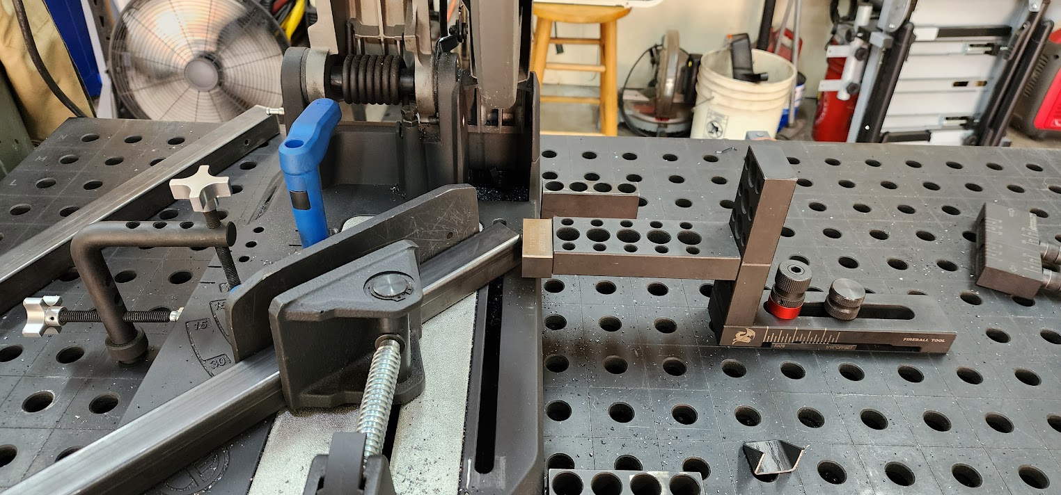
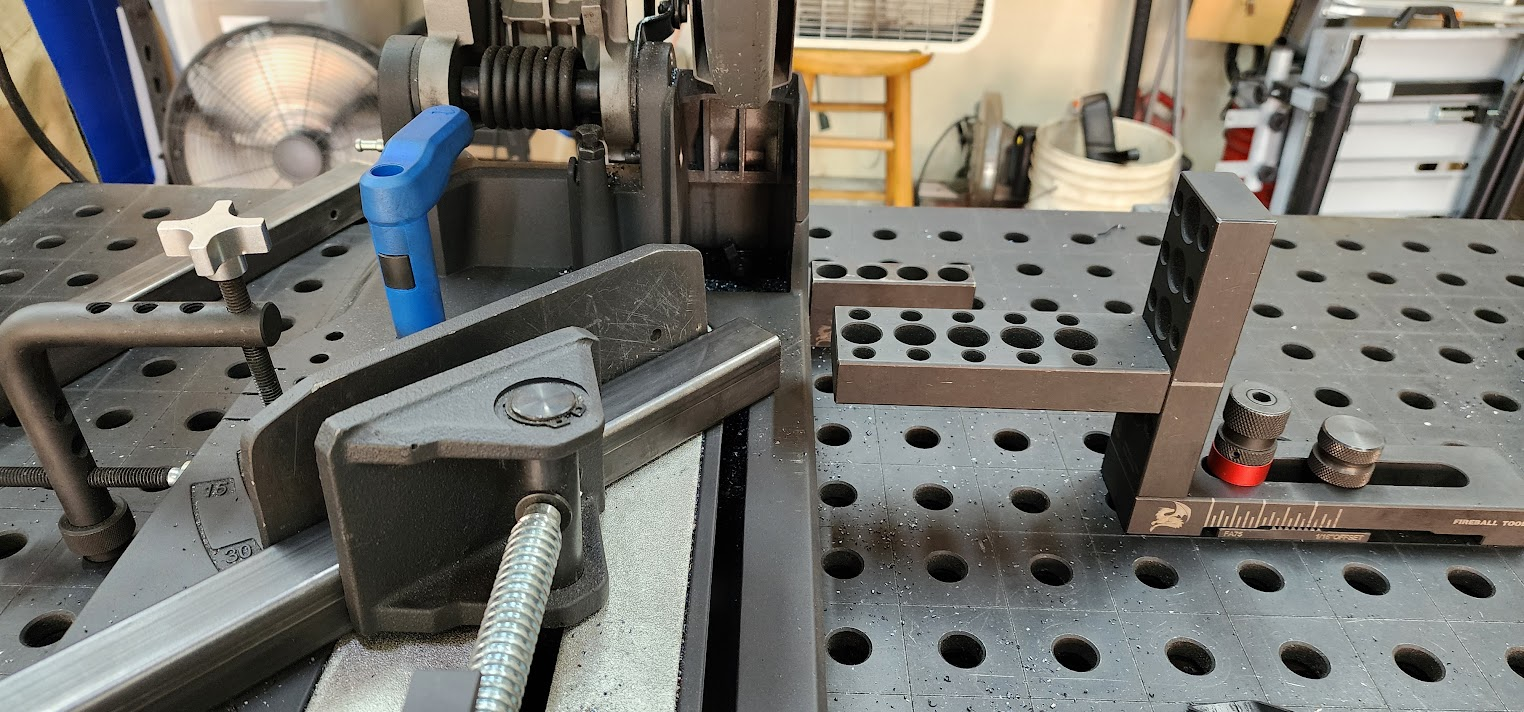
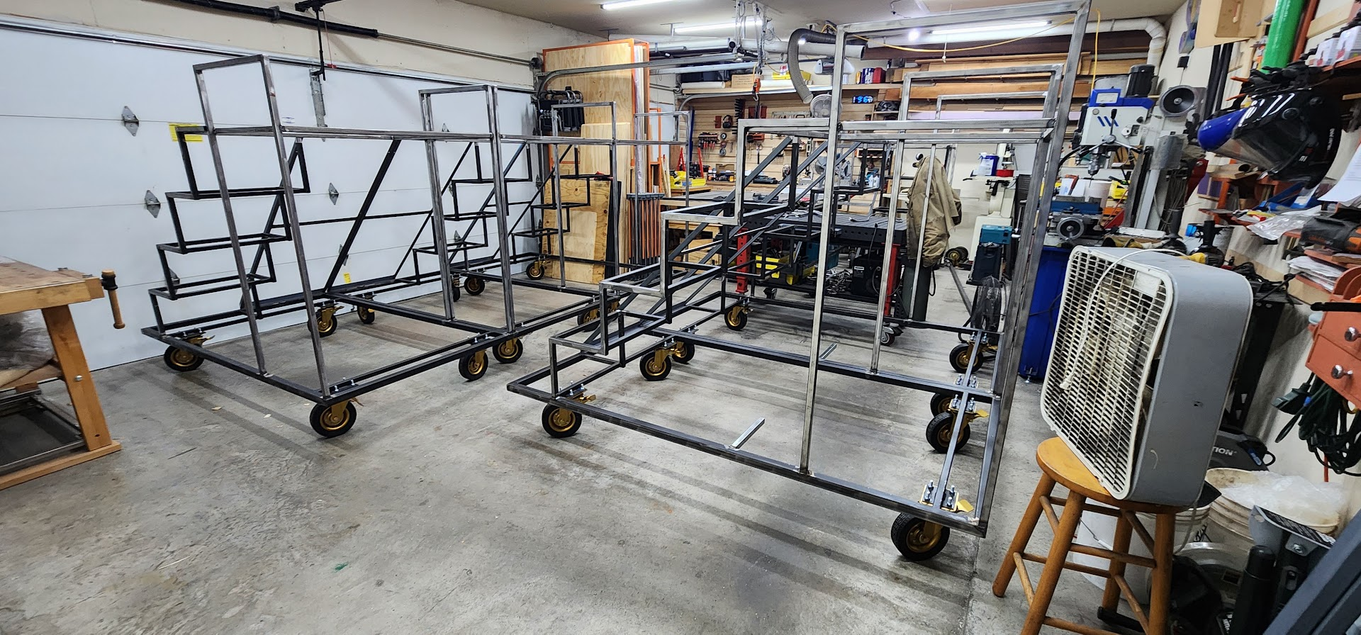
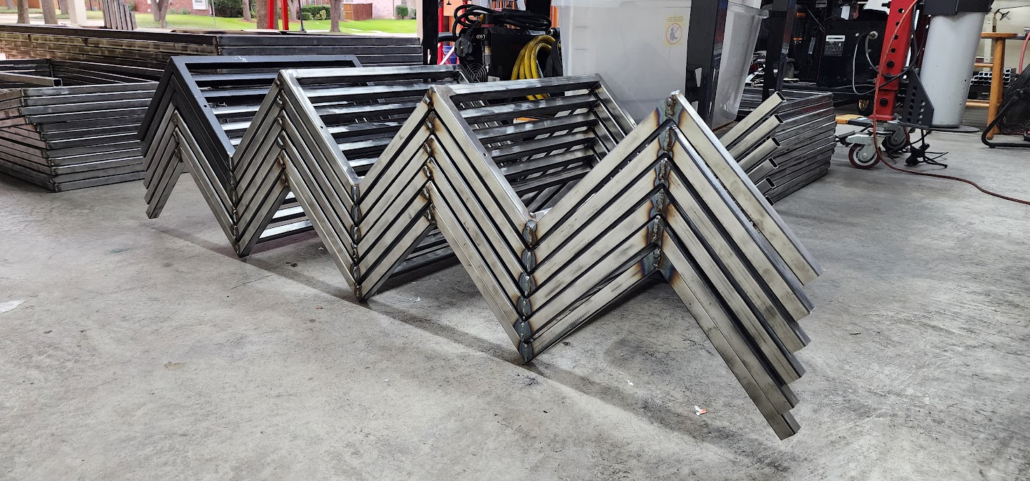
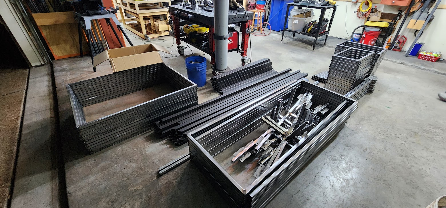
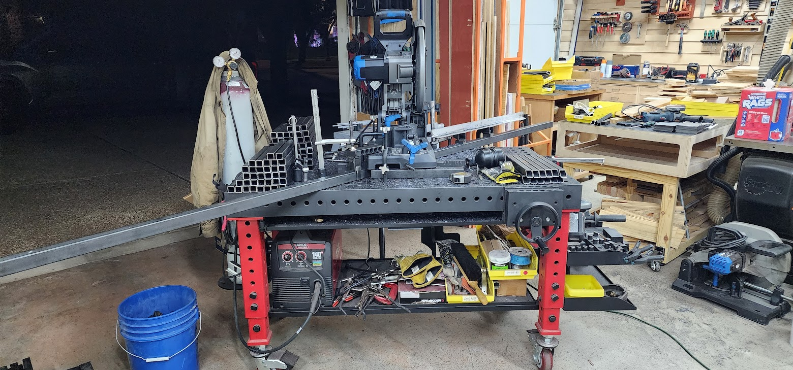
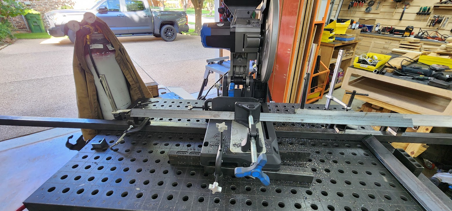
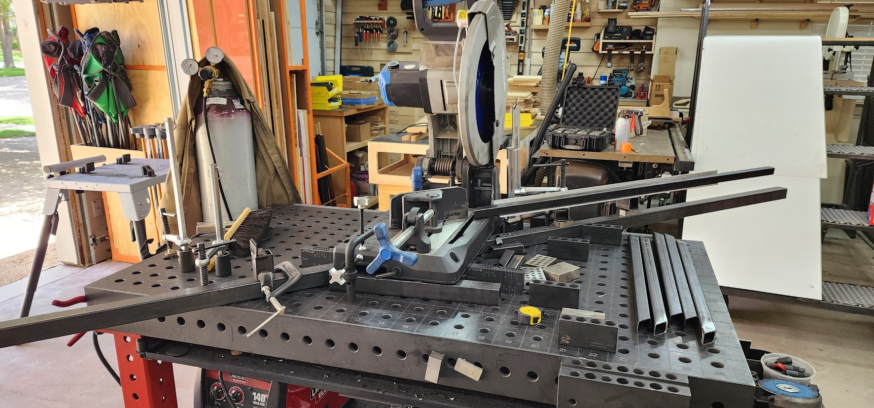
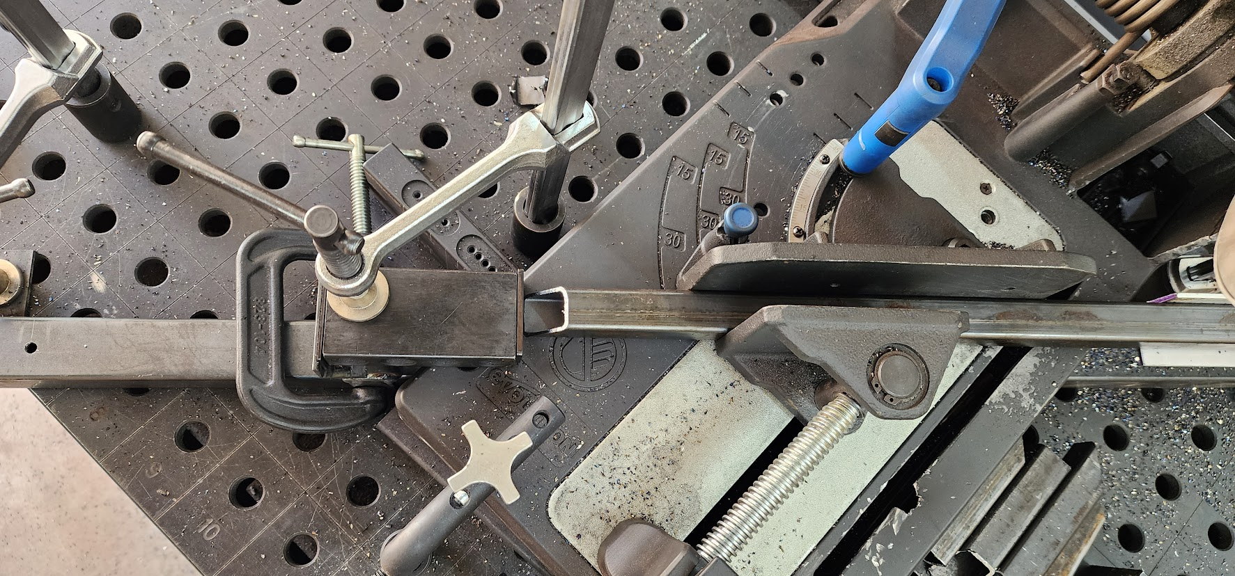
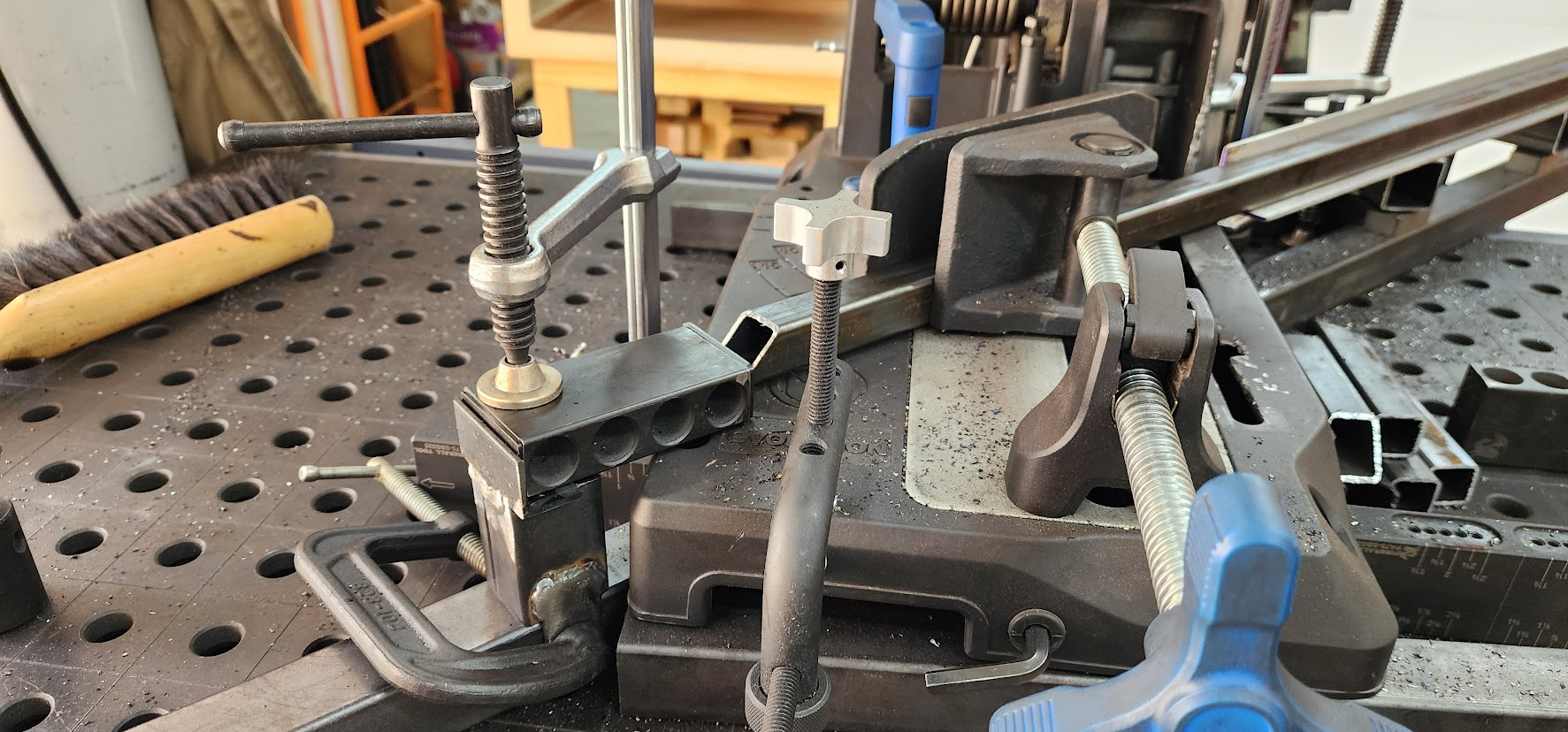
    Manufacturing phase: chop-saw fences dialed in, hundreds of pieces cut toward ~600 parts for twelve identical props.

  • June 12, 2026

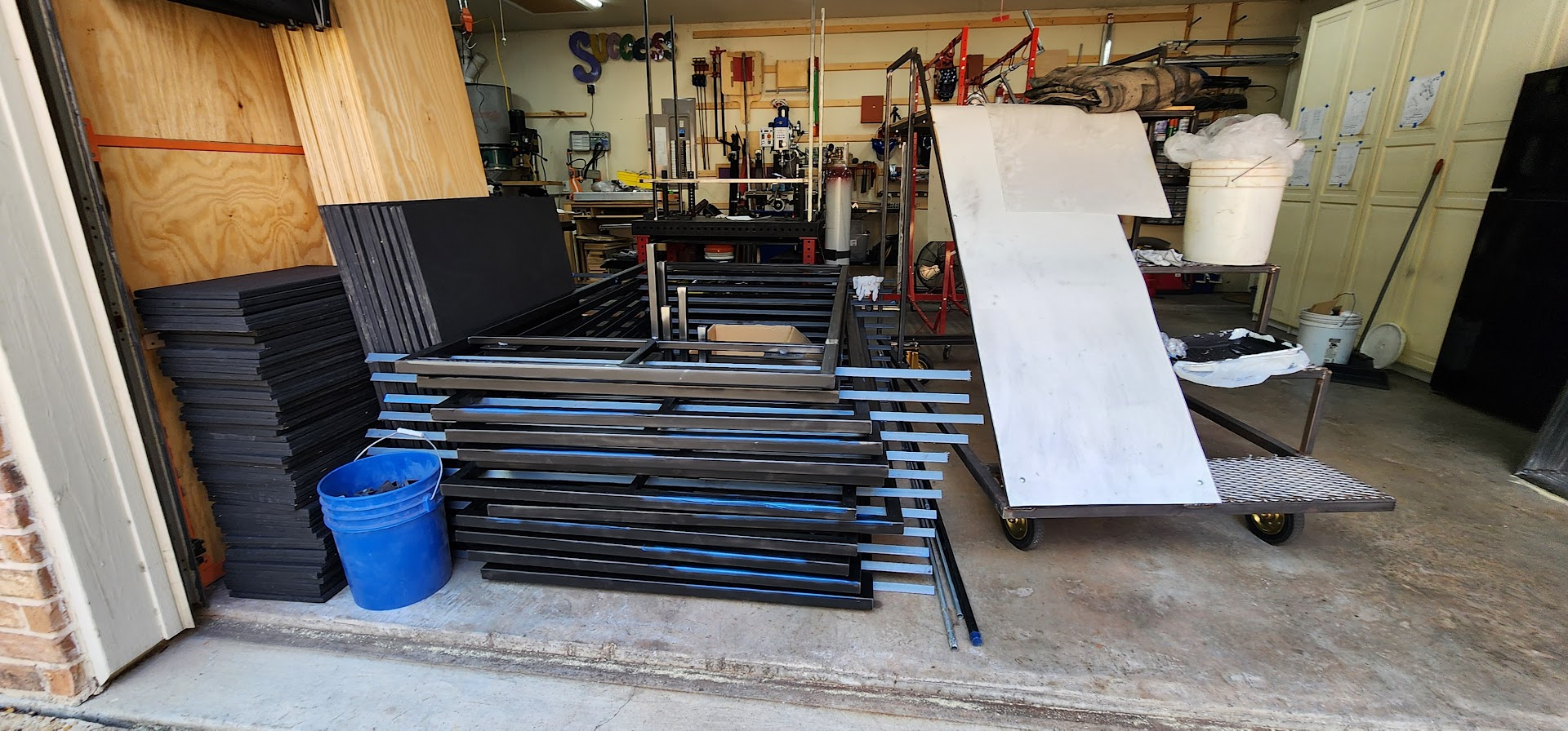
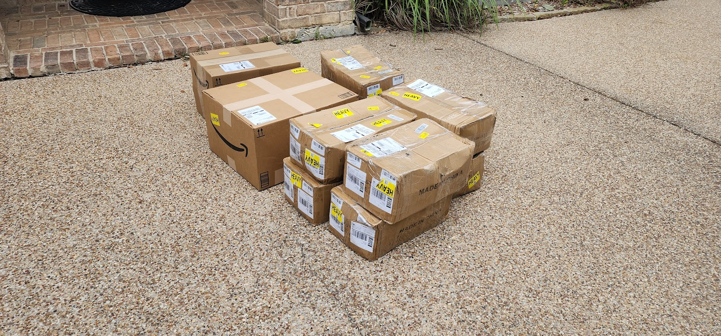
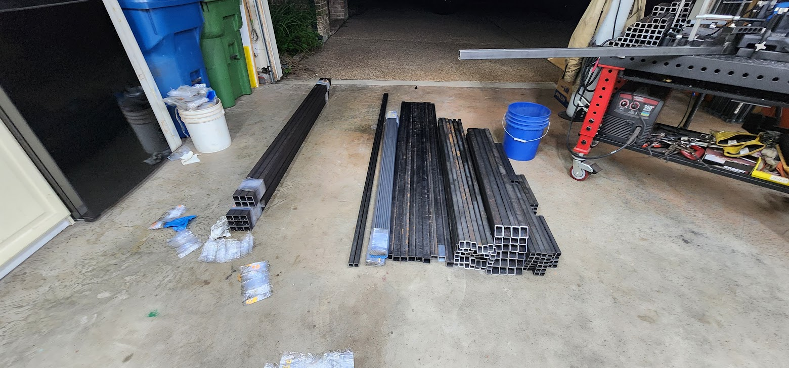
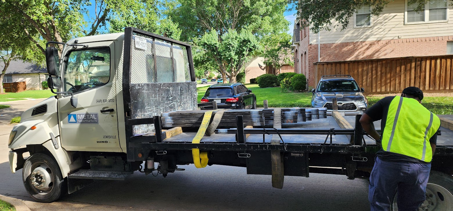
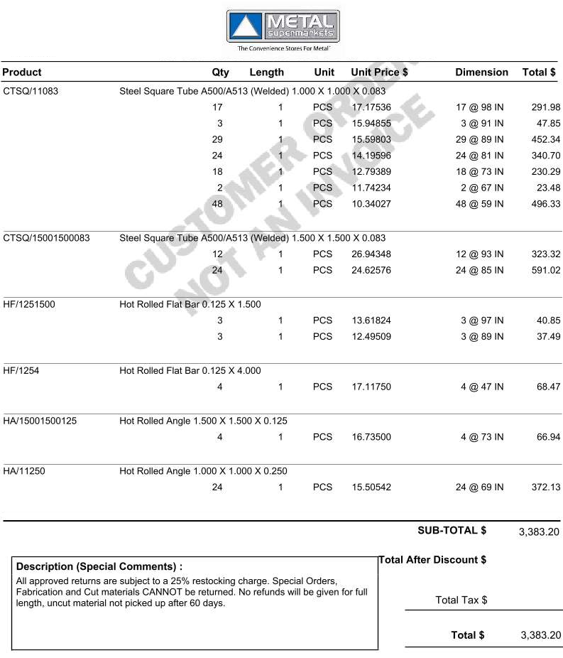
    Metal delivery — 215 pieces of stock (~$3,300) unloaded and sorted in the workshop.

  • June 6–11, 2026

    Final CAD and coroplast sheet layouts; dock stages halved to one 4 × 8 section each; front screens increased to 10; metal order placed.

  • May 22–26, 2026

    Prototype platform rebuilt — larger 4 × 3 ft deck, lower height, flag trough; second school test at Audition Camp.

  • May 14–17, 2026

    First school user test: slide angle validated, platform comfort flagged; version 2 CAD mockups drawn for a lower, roomier top deck.

  • May 8, 2026

    Prototype declared ready to leave the shop for its first real-world evaluation with students and the band director.

  • April 2026

    First full prototype assembled and shared with leadership (~$700/prop estimate); build logs cover wheels, platforms, and slide; show reveal parent/student meeting.

  • March 2026

    Prototype build begins in the workshop — foundation framing and early fabrication.

  • February 2026

    Props kickoff with band leadership; Relativity-inspired stair/slide concept; first CAD mockups and design review (8–12 mirrored props).

Progress Blog

Thursday, July 9, 2026

July 9, 2026 – A Plywood Run

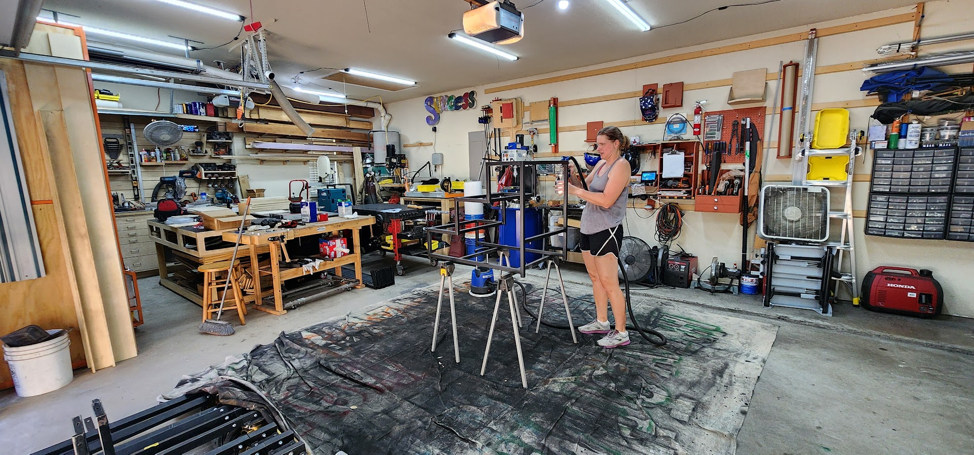
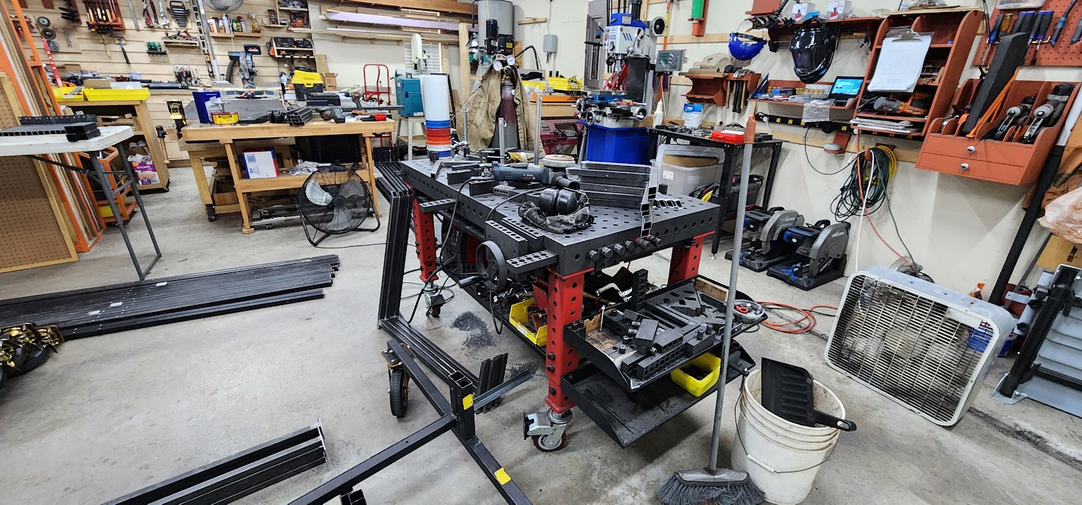
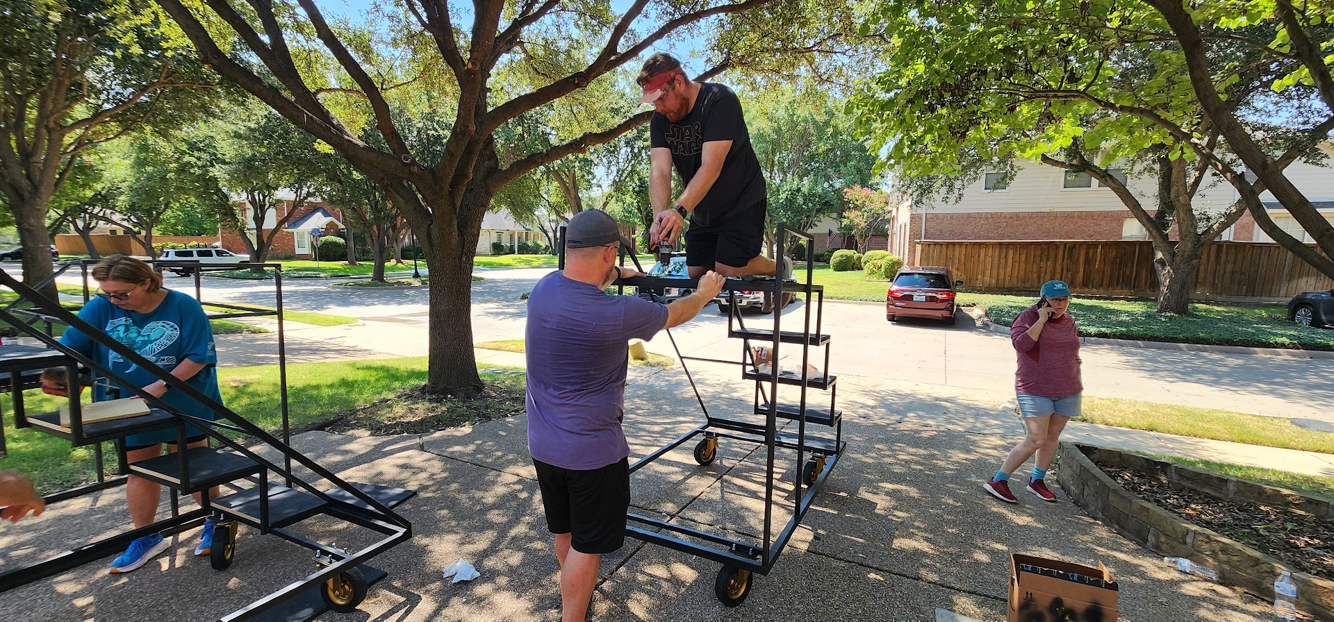
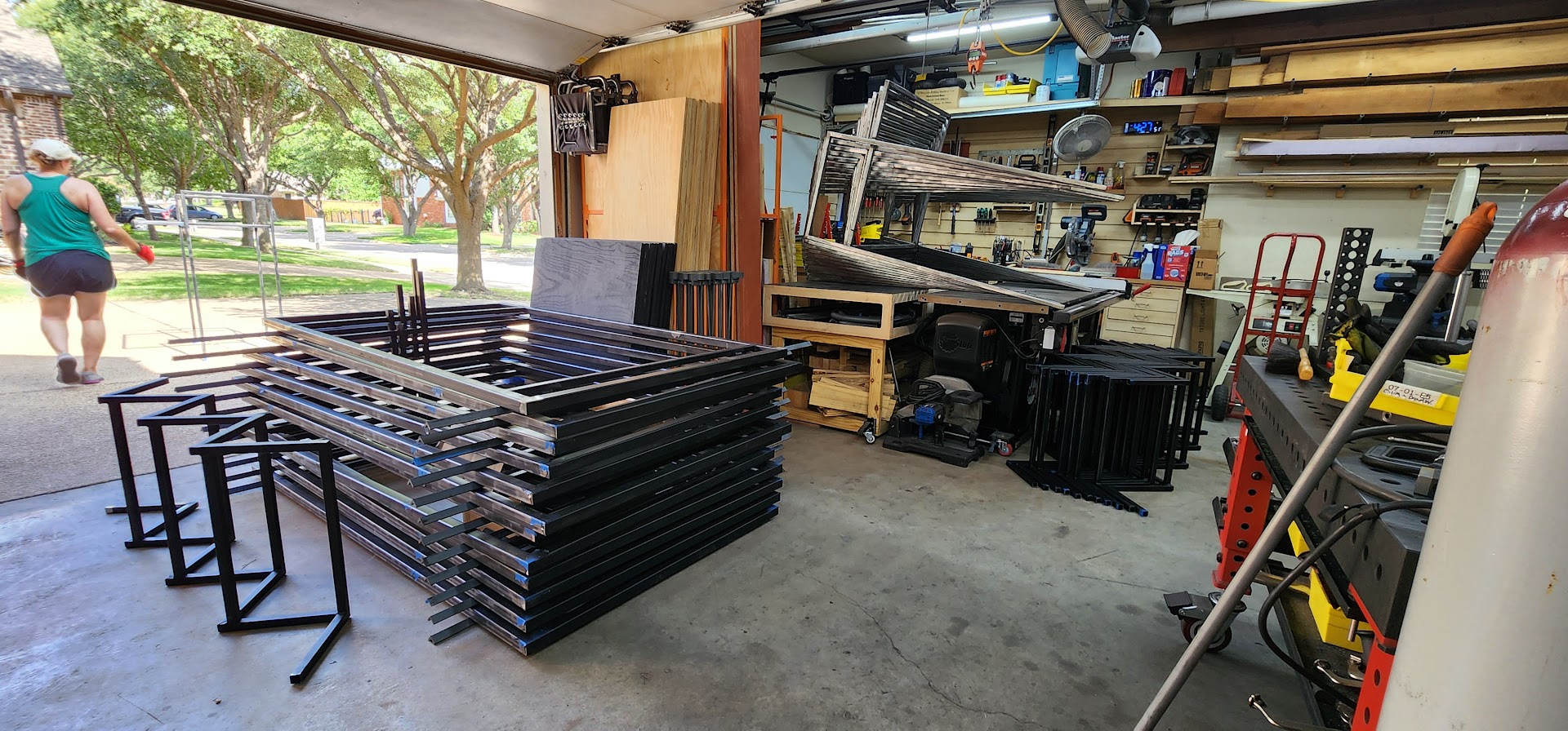
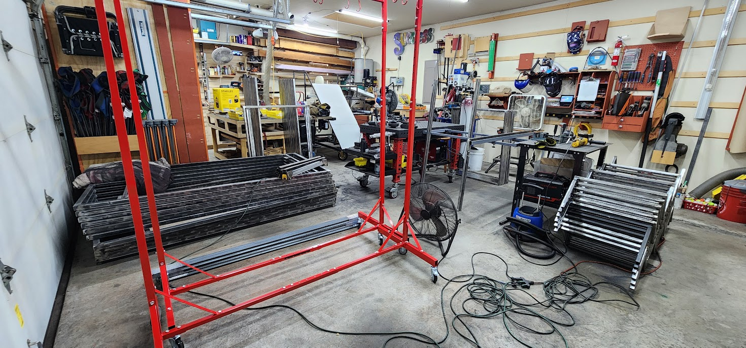
Today's work session took place outside the Maker At Play workshop.

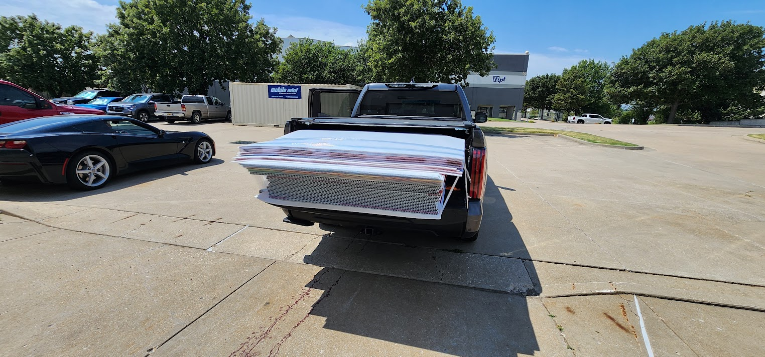
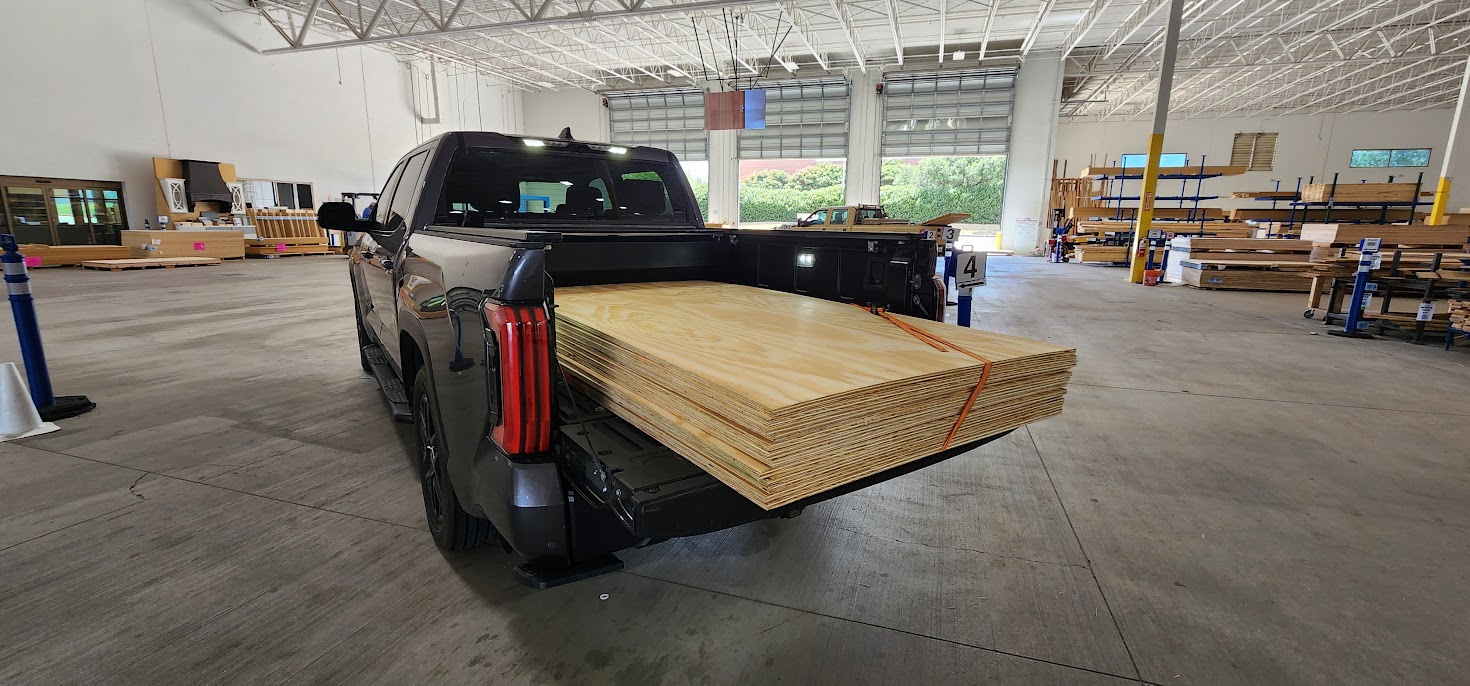
With Saturday's volunteer workday quickly approaching, one of the major tasks will be cutting all of the plywood for the props. The plan is to cut the twelve sheets into the required parts, drill the mounting holes, and get everything painted. Before any of that could happen, though, I needed to go pick up the plywood.

The easiest option would have been to make a quick trip to the local Home Depot and load twelve sheets into the truck.

But I've learned over the years that convenience isn't always the best choice when it comes to plywood.

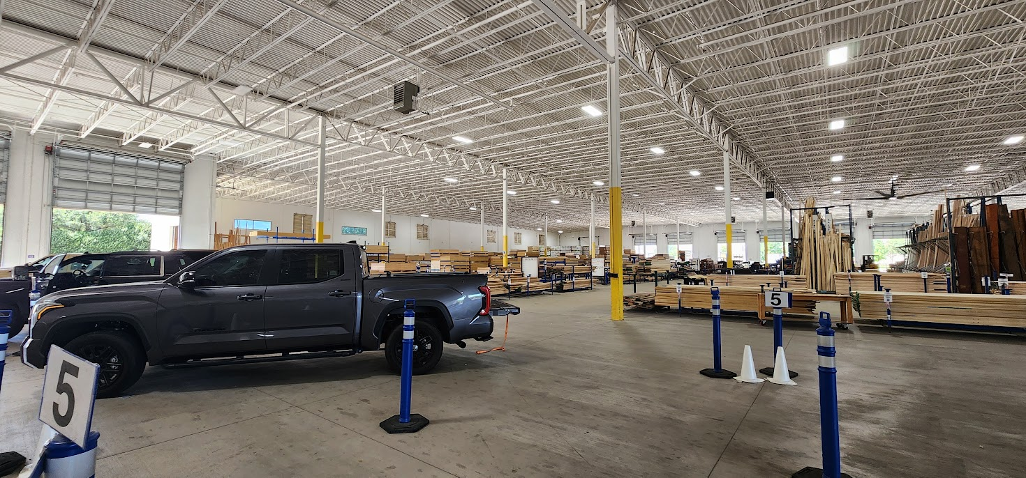
The plywood at the big box stores tends to be more expensive and the quality can be hit or miss. Last year, while building my miter saw station, I discovered The Plywood Company of Fort Worth. They carry a much larger selection of plywood and hardwoods, and I've found both the quality and the pricing to be considerably better.

The only downside is the drive.

So today became a road trip to Fort Worth instead of a quick run across town.

By the end of the day, the truck was loaded with all twelve sheets of plywood, and another important item was checked off the project list.

Now we're ready for Saturday.

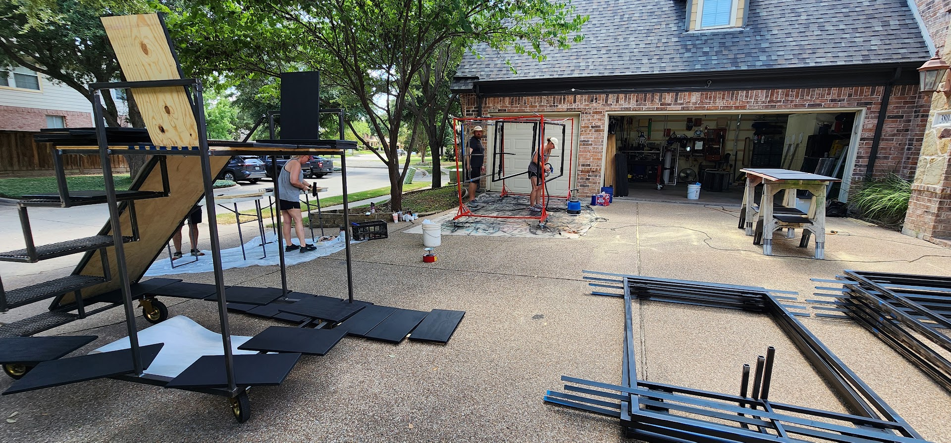
With the steel prepped, the paint ready, and the plywood stacked in the workshop, everything is in place for our first volunteer workday. I'm looking forward to seeing how much progress we can make with a full crew helping build the props.

Wednesday, July 8, 2026

July 8, 2026 – Many Hands Make Light Work

Tonight the Maker At Play workshop welcomed another band dad to help with the prop build.

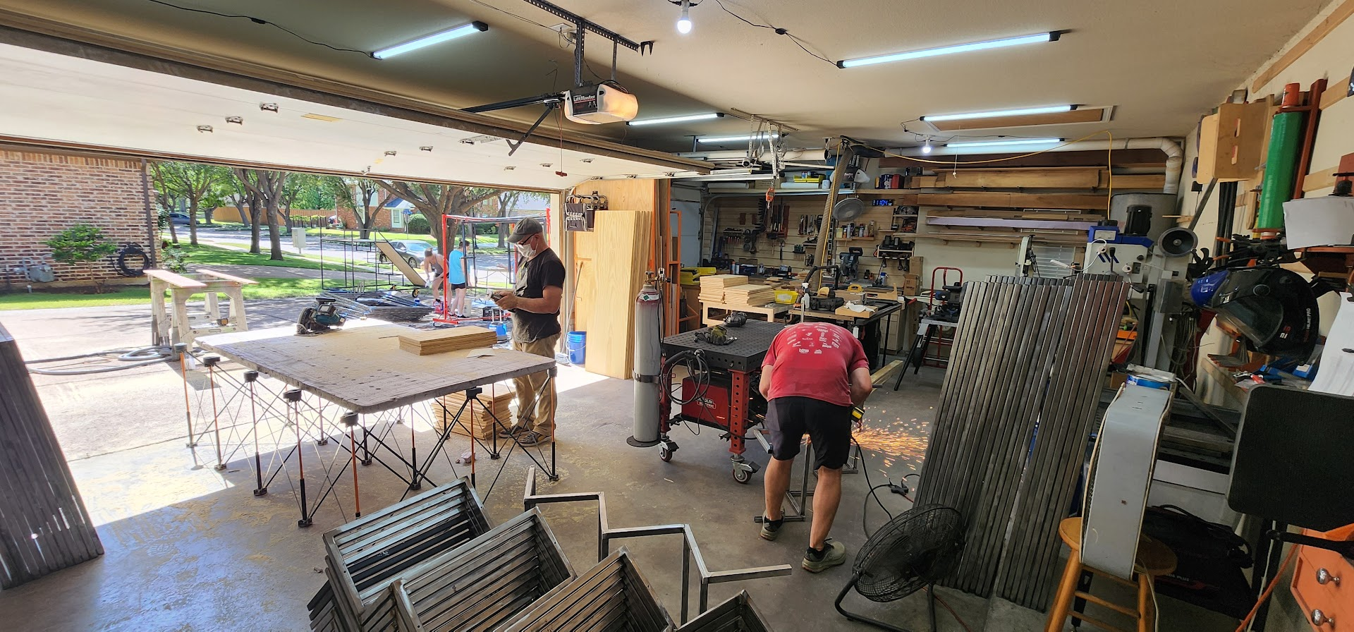
With our first parent prop workday coming up on Saturday, the goal was to get as many parts as possible ready for painting and final assembly.

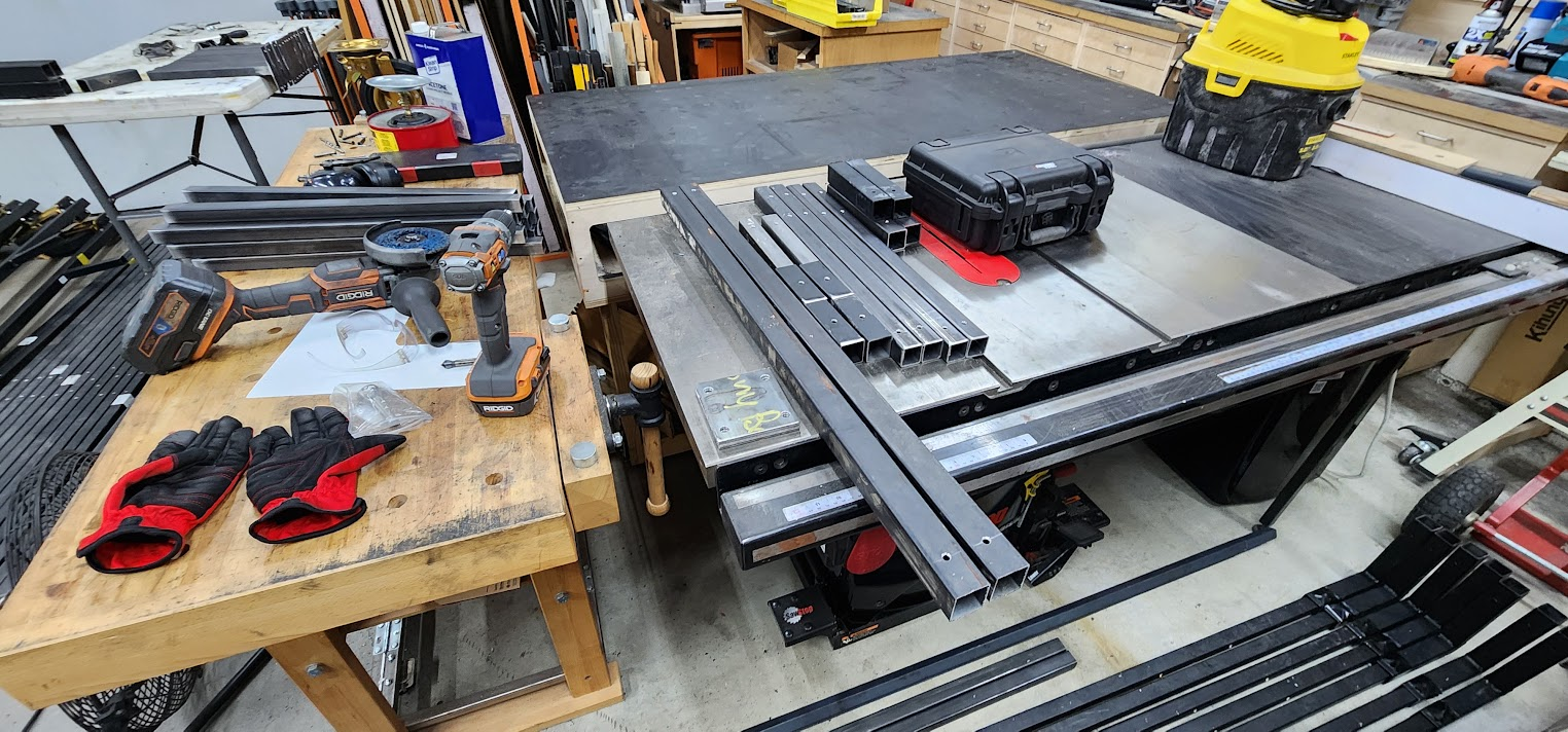
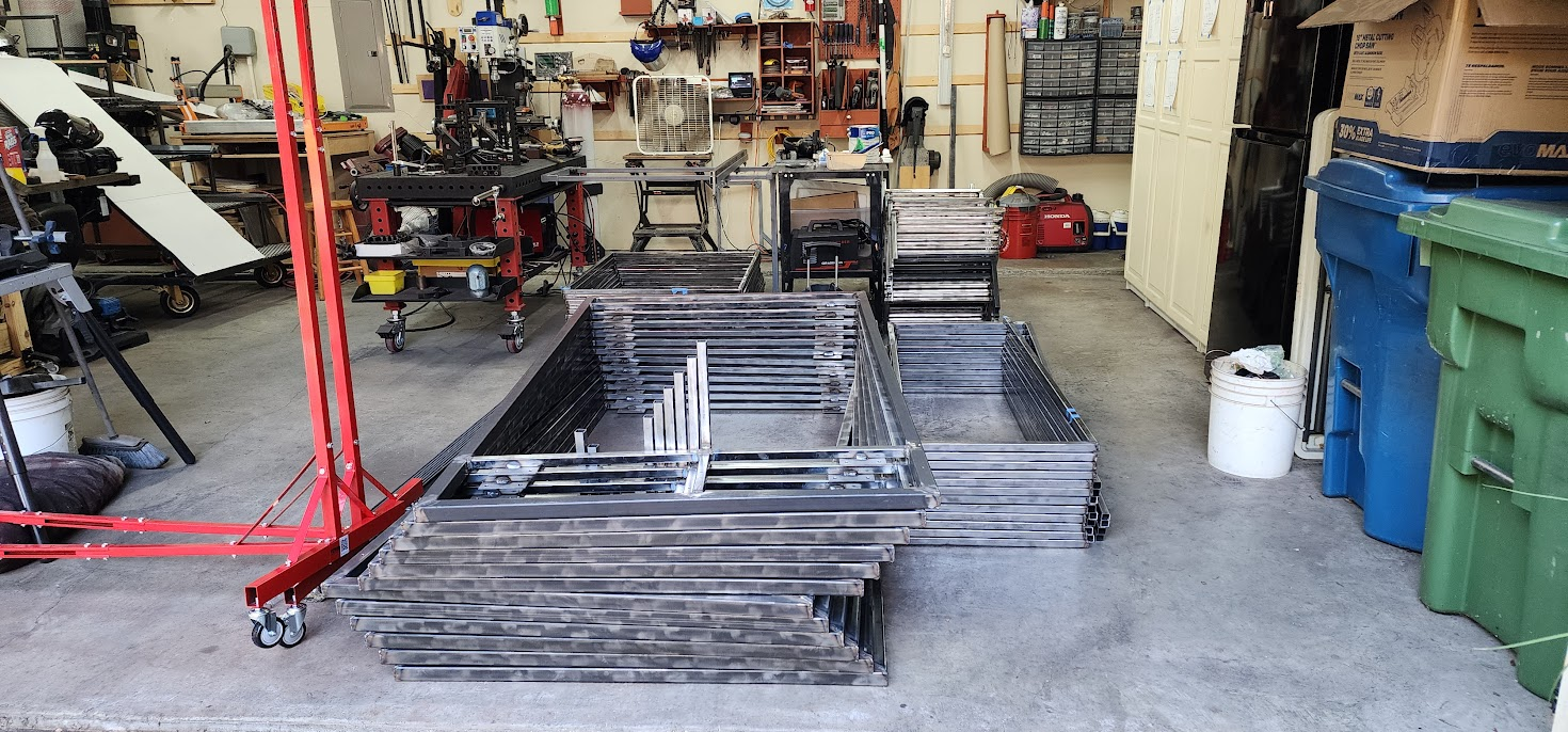
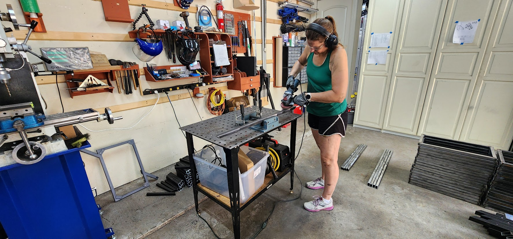
Our primary task was grinding the welds on all twelve base assemblies so they'd be ready for paint this weekend. At the same time, we also cleaned up the platform assembly parts, preparing them for welding in the next phase of production.

Having an extra set of hands made a huge difference.

Each base assembly is large and awkward to handle by yourself. Our workflow quickly settled into a rhythm: lift a base onto the sawhorses, grind all of the welds on the top side, flip it over, grind the bottom side, then stack the finished base on the shop floor before moving on to the next one.

It's one of those jobs that's hard to appreciate until you've done it. Grinding isn't particularly exciting, but it's what transforms a rough fabrication into something that's ready for primer and paint. Taking the time now also makes the finished props look much cleaner.

By the end of the evening, all of the base assemblies had been prepped for Saturday's painting session, and the platform parts were ready for welding.

With the first volunteer workday just around the corner, everything is coming together for the next big push.

Open on YouTube

Tuesday, July 7, 2026

July 7, 2026 – A Major Milestone

Tonight's goal was to finish the remaining six stair assemblies.

After spending the past few evenings developing the fixture and refining the welding sequence, these six came together surprisingly fast. Once you have a good system, making six of something really isn't much more work than making one. The time is in figuring out the process. Once that's solved, production becomes almost routine.

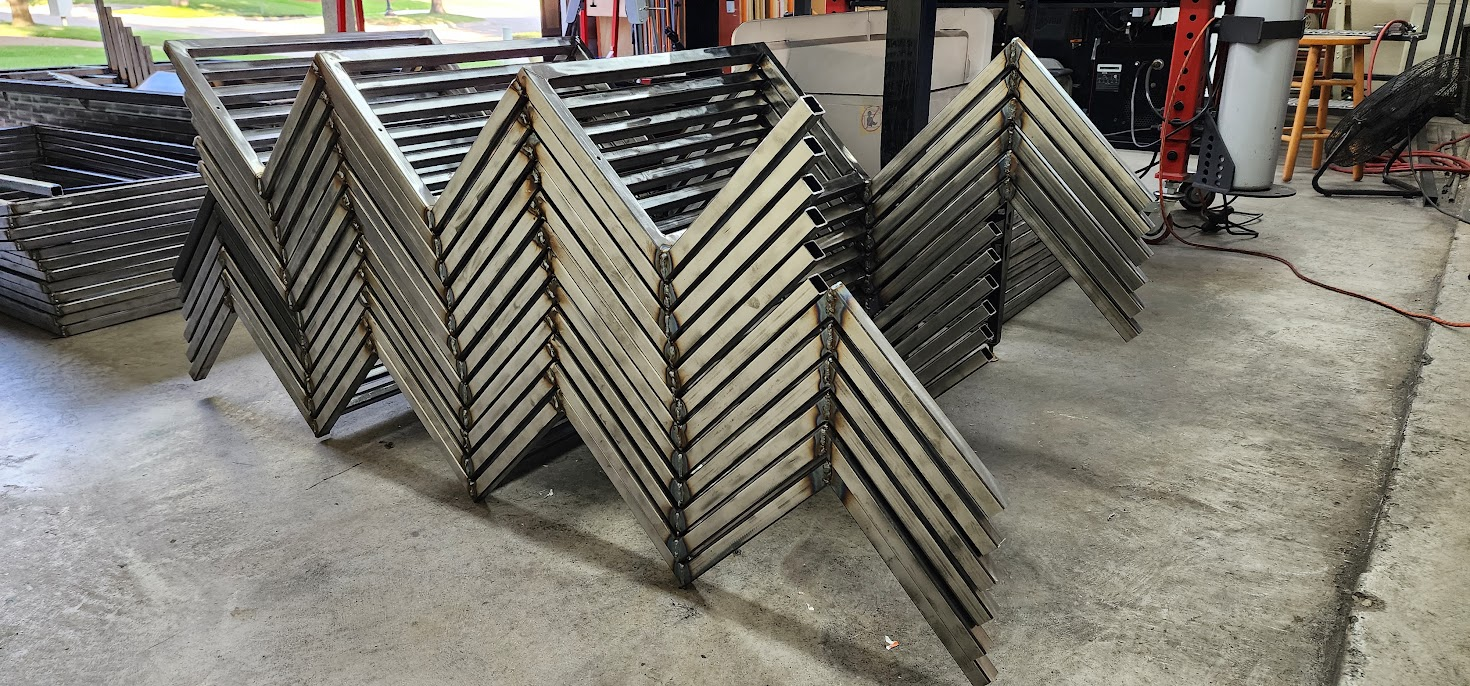
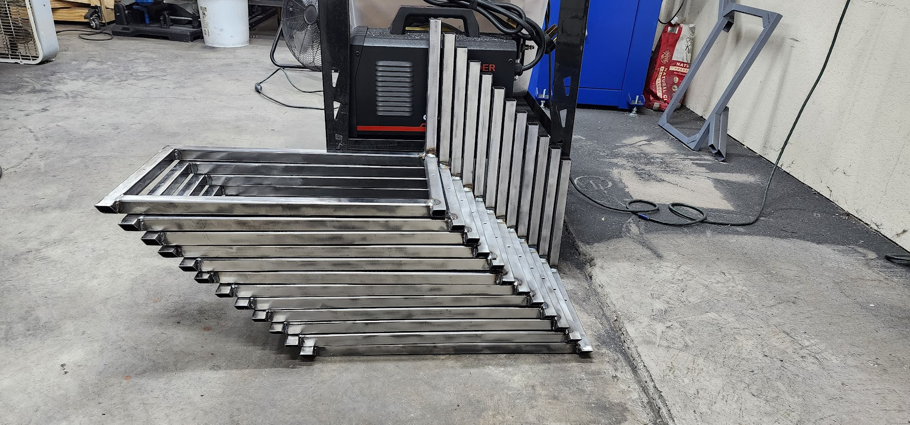
By the end of the evening, all twelve three-step stair assemblies were complete.

That makes this one of the biggest milestones of the project so far.

Each stair assembly is made up of 20 individual pieces of steel. Completing all twelve means 240 of the roughly 600 total metal pieces that make up these props have now been transformed into finished assemblies.

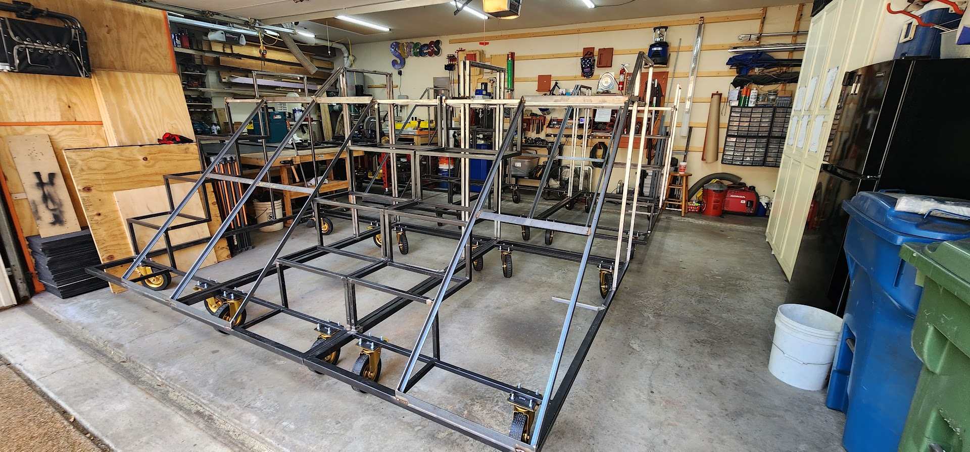
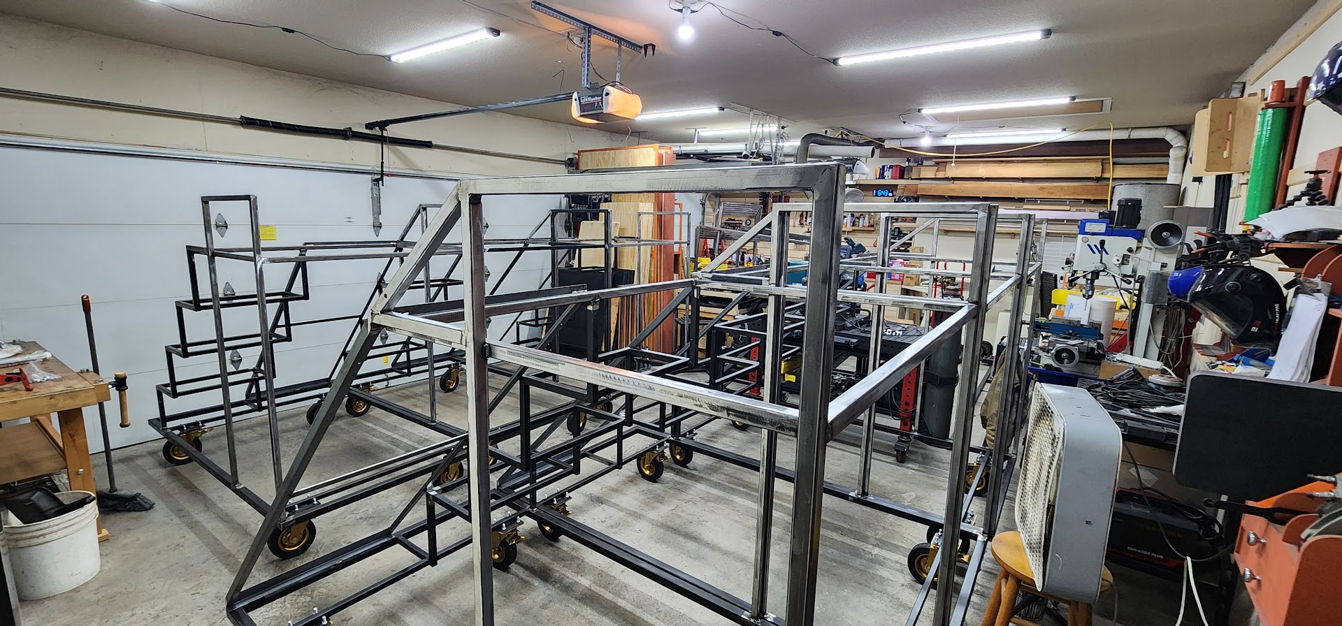
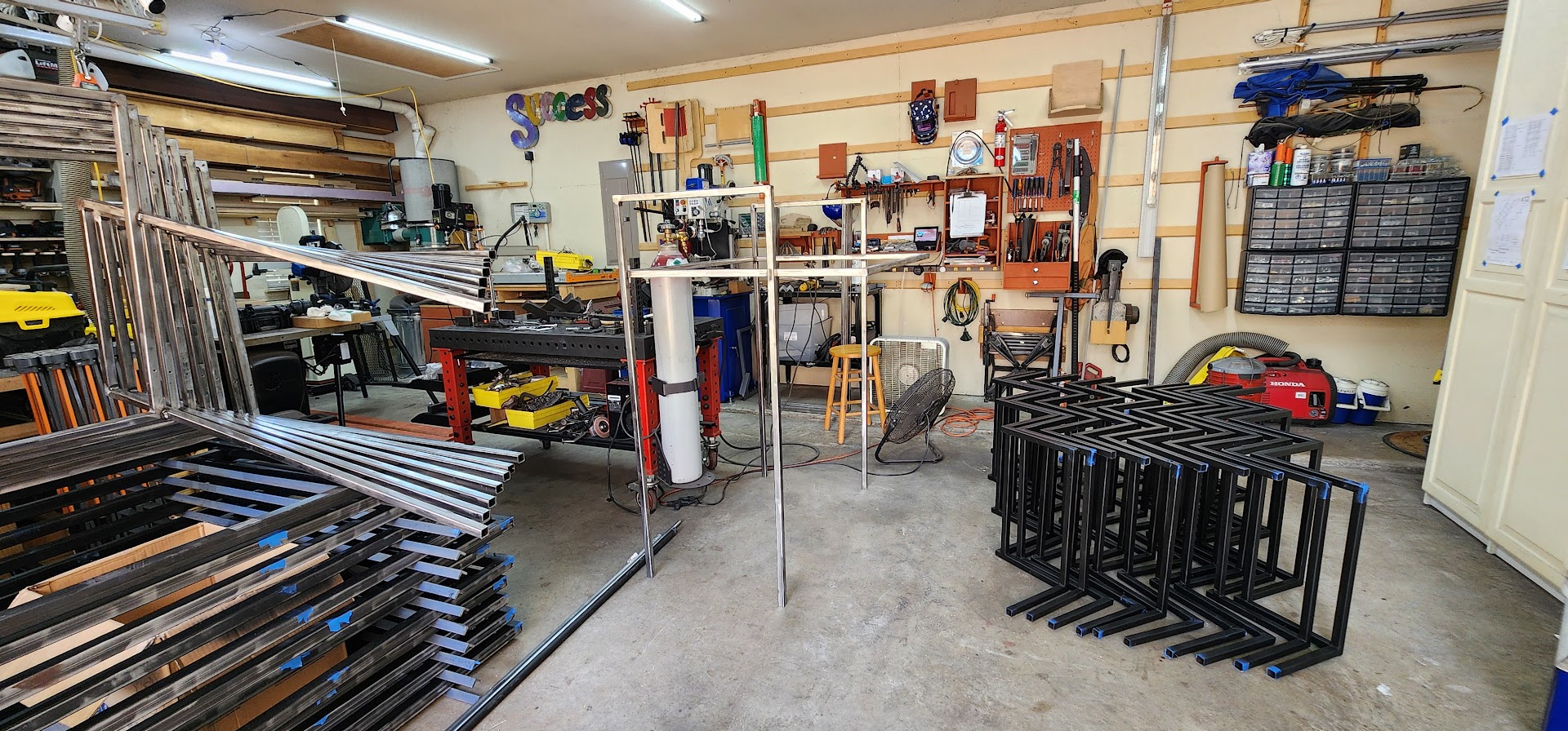
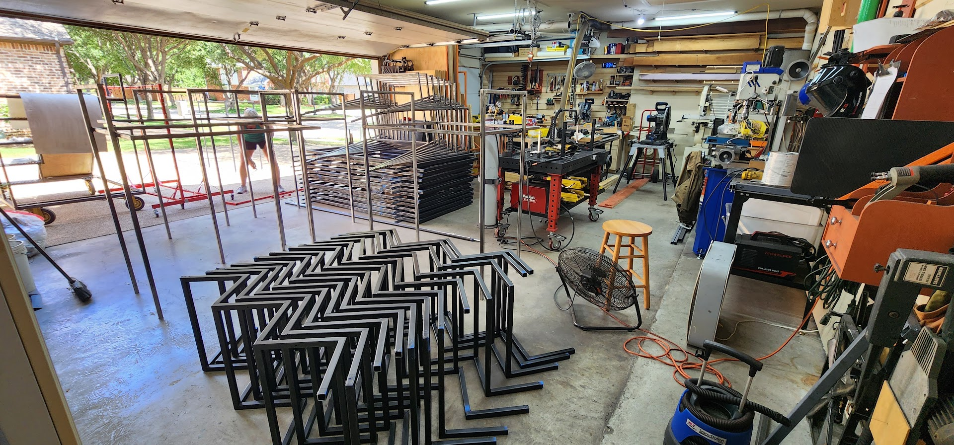
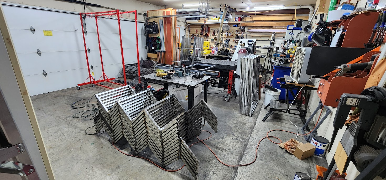
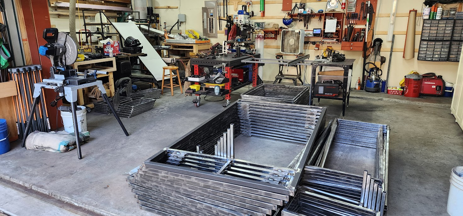
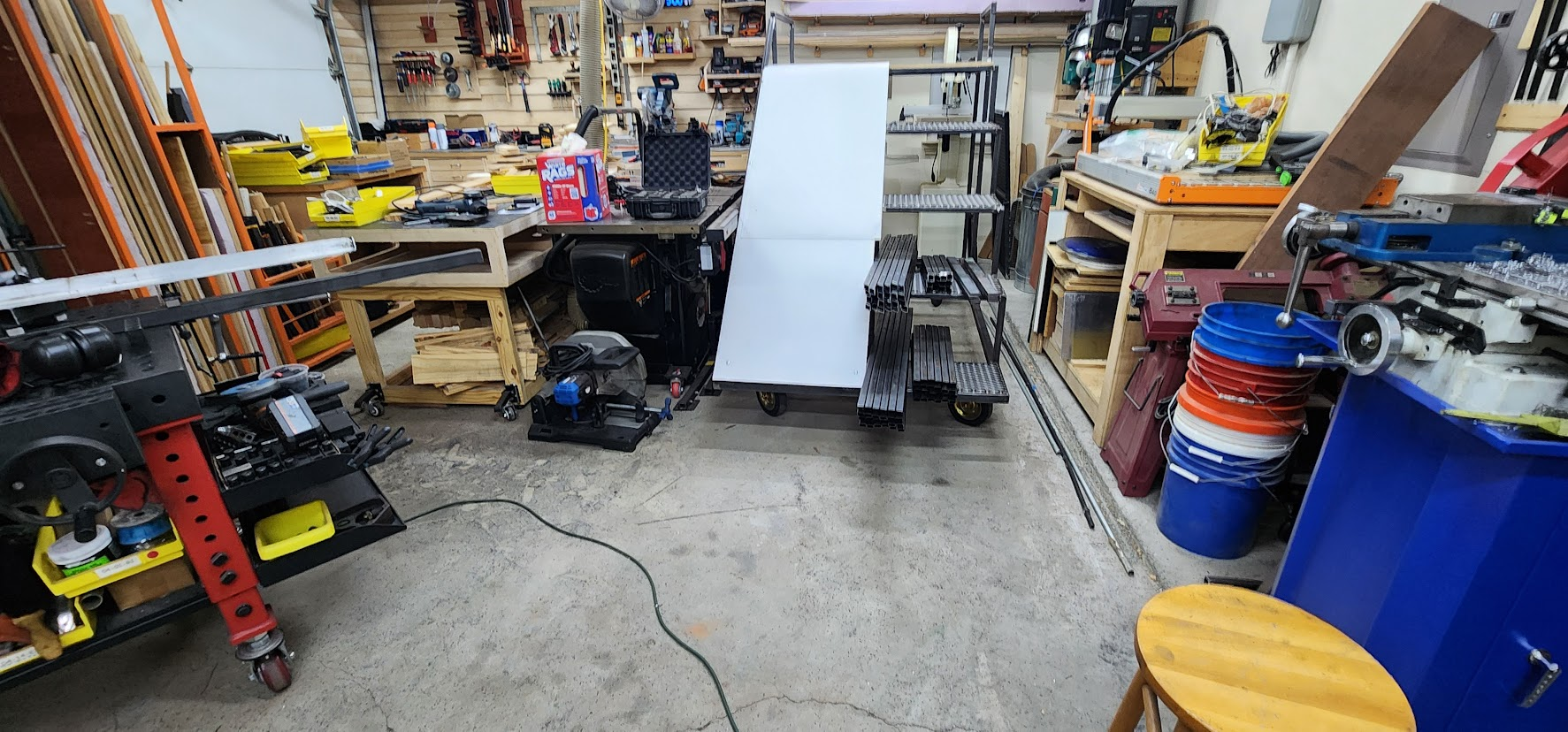
Standing back and looking around the workshop, it's amazing how much has changed over the past few weeks. The pile of stock steel that covered the shop floor when it was delivered has almost completely disappeared. In its place are neatly stacked subassemblies waiting for final assembly.

It's rewarding to reach a point where the project starts feeling less like cutting and welding random pieces of metal and more like building actual props.

There's still plenty of work ahead, but another major building block is complete, and the finish line is beginning to feel a little closer.

Open on YouTube

Monday, July 6, 2026

July 6, 2026 – Halfway Through the Stair Assemblies

Another productive evening in the Maker At Play workshop.

Tonight's goal was simple: keep building stair assemblies.

Before I could start welding, I spent some time grinding several of the individual step assemblies to prepare the joints. It's one of those jobs that's easy to overlook, but clean joints make for better welds and less cleanup later.

Once everything was prepped, I welded together five more three-step stair assemblies.

After completing the first assembly, I settled into a good rhythm. Each stair assembly requires welding four vertical support pieces, with welds on all four sides and both ends of every support. That's a lot of welding for each assembly, but once I established the sequence, I could work efficiently without constantly repositioning the assembly or second-guessing what weld came next.

About three assemblies into the evening, production came to a temporary stop.

I ran out of welding wire.

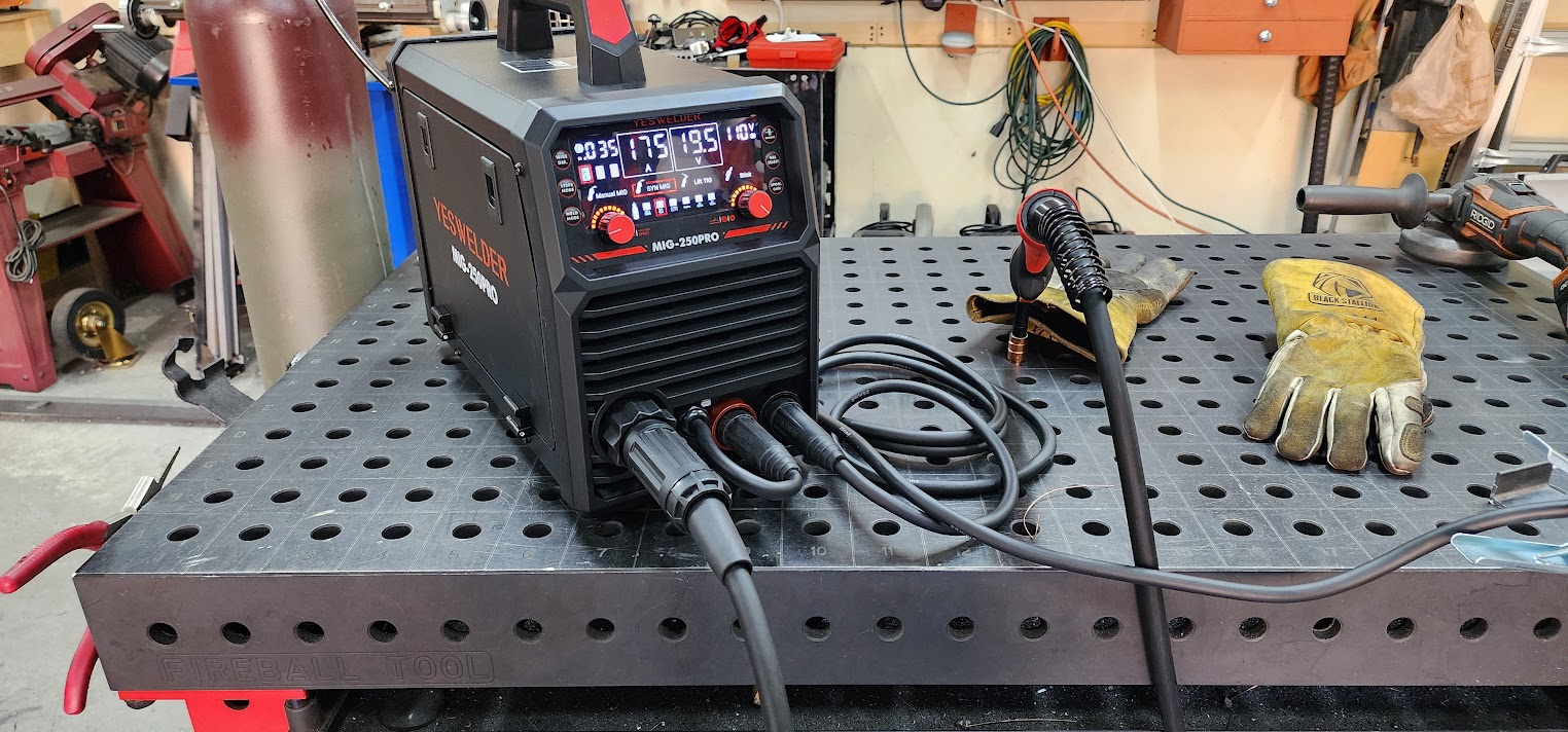
Changing the spool isn't normally a big deal, but my welder lives underneath my welding table, which isn't exactly the most convenient place to access it. Swapping wire while crouched under the table wasn't the highlight of the evening, but after a few minutes I was back in business.

By the end of the night, five more stair assemblies were complete. Combined with the one I finished yesterday, that brings the total to six completed stair assemblies, leaving just six more to build.

Halfway there.

Tomorrow's goal is to finish the remaining six and check another major assembly off the list.

Open on YouTube

Sunday, July 5, 2026

July 5, 2026 – Building the Stairs

Another productive day in the Maker At Play workshop.

The first bit of good news arrived before I even struck an arc. The shipment of 12 sets of 8-inch casters showed up today. One thing I've learned on projects like this is to stay ahead of the material schedule. The last thing I want is to finish a portion of the build only to have everyone standing around waiting for parts to arrive.

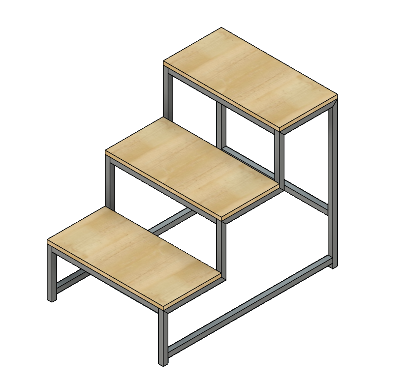
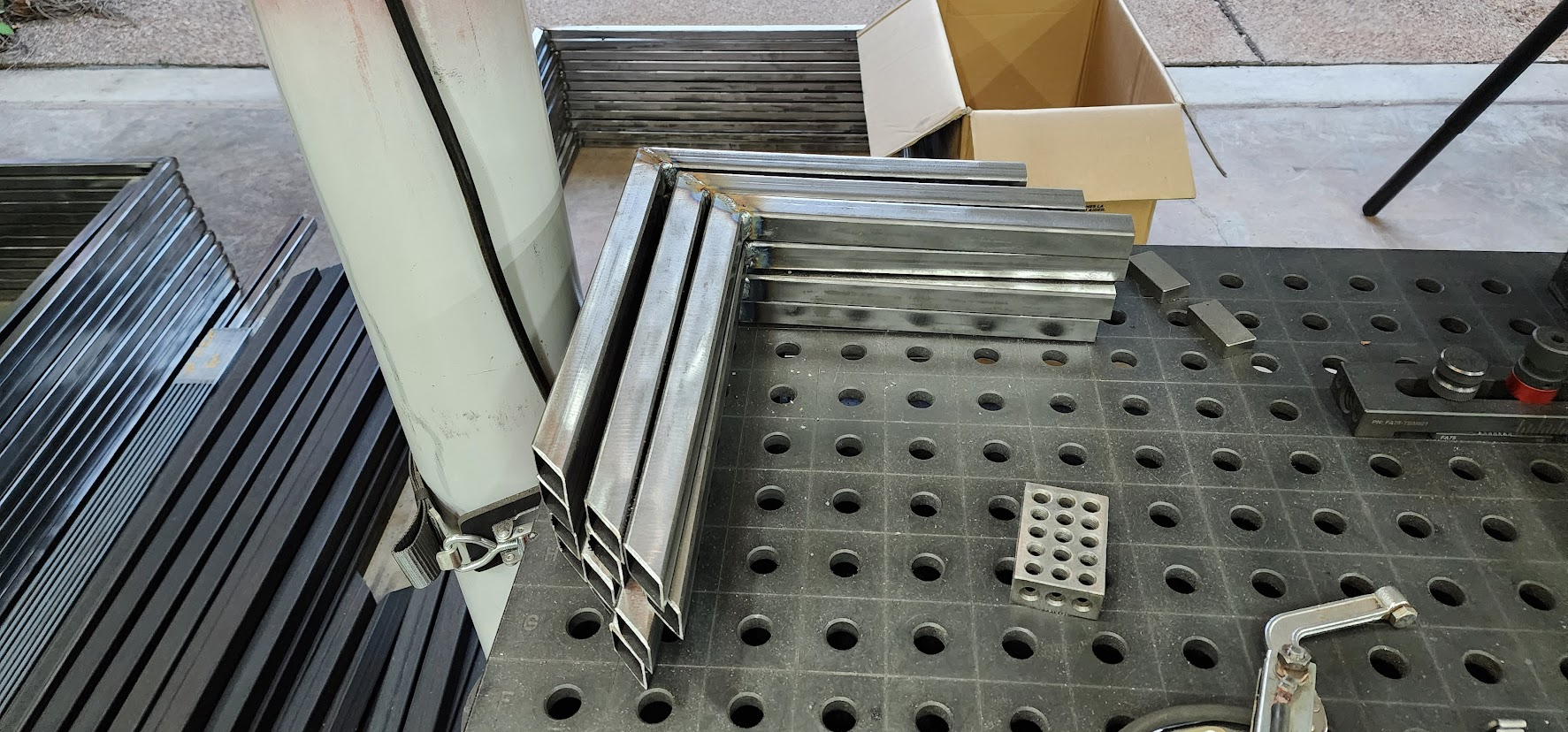
I also finished welding the last six top step subassemblies, which cleared the way for the next major phase of the project: assembling the full three-step stair sections.

This was the point where the project literally started going vertical.

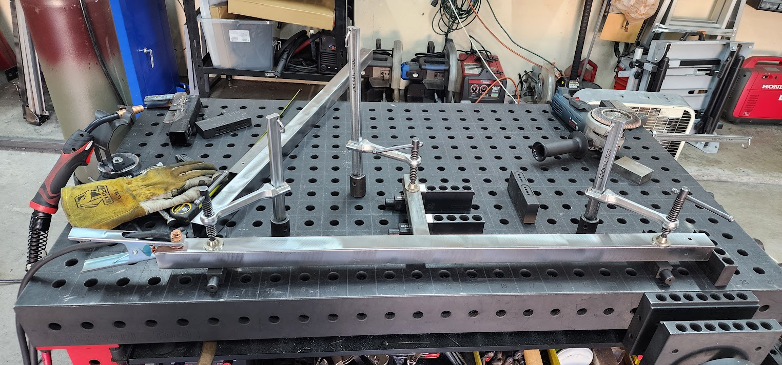
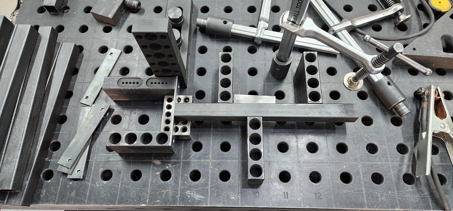
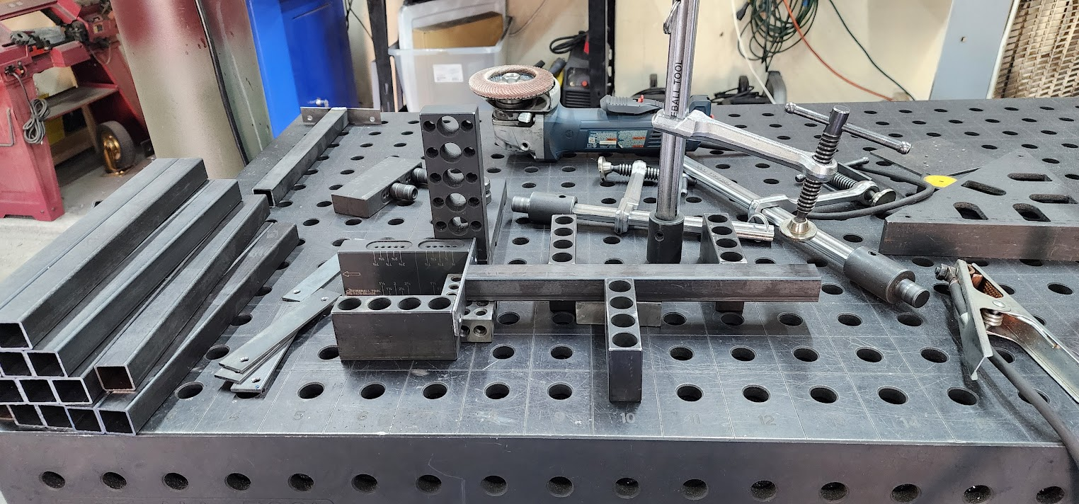
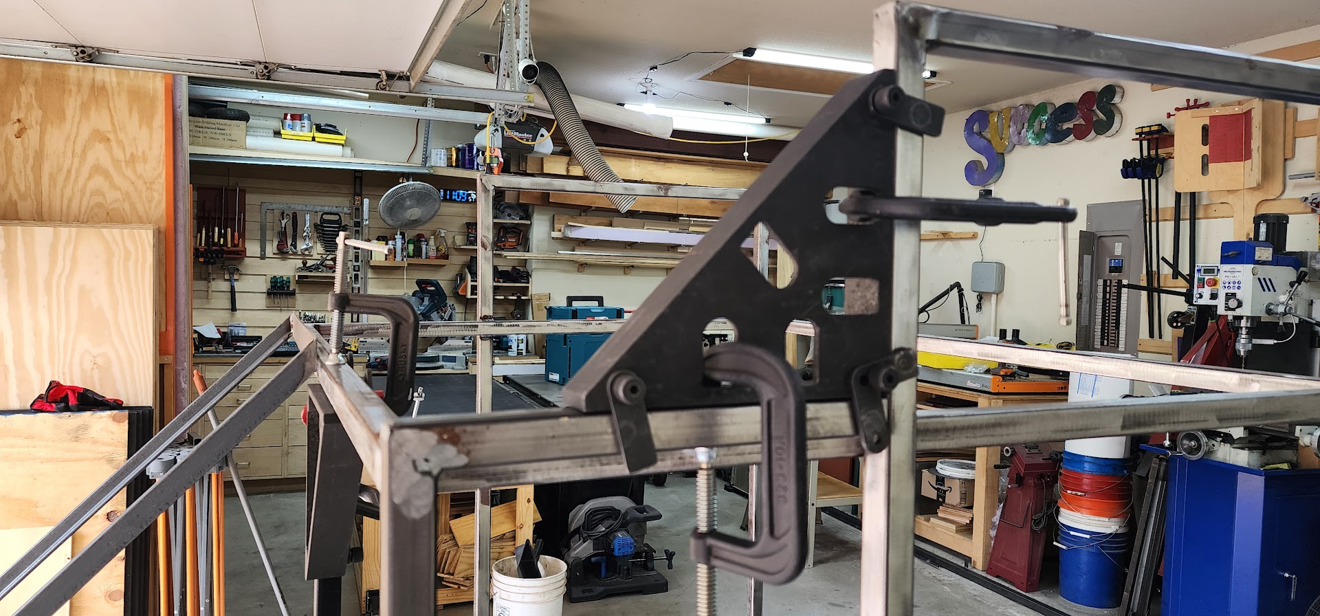
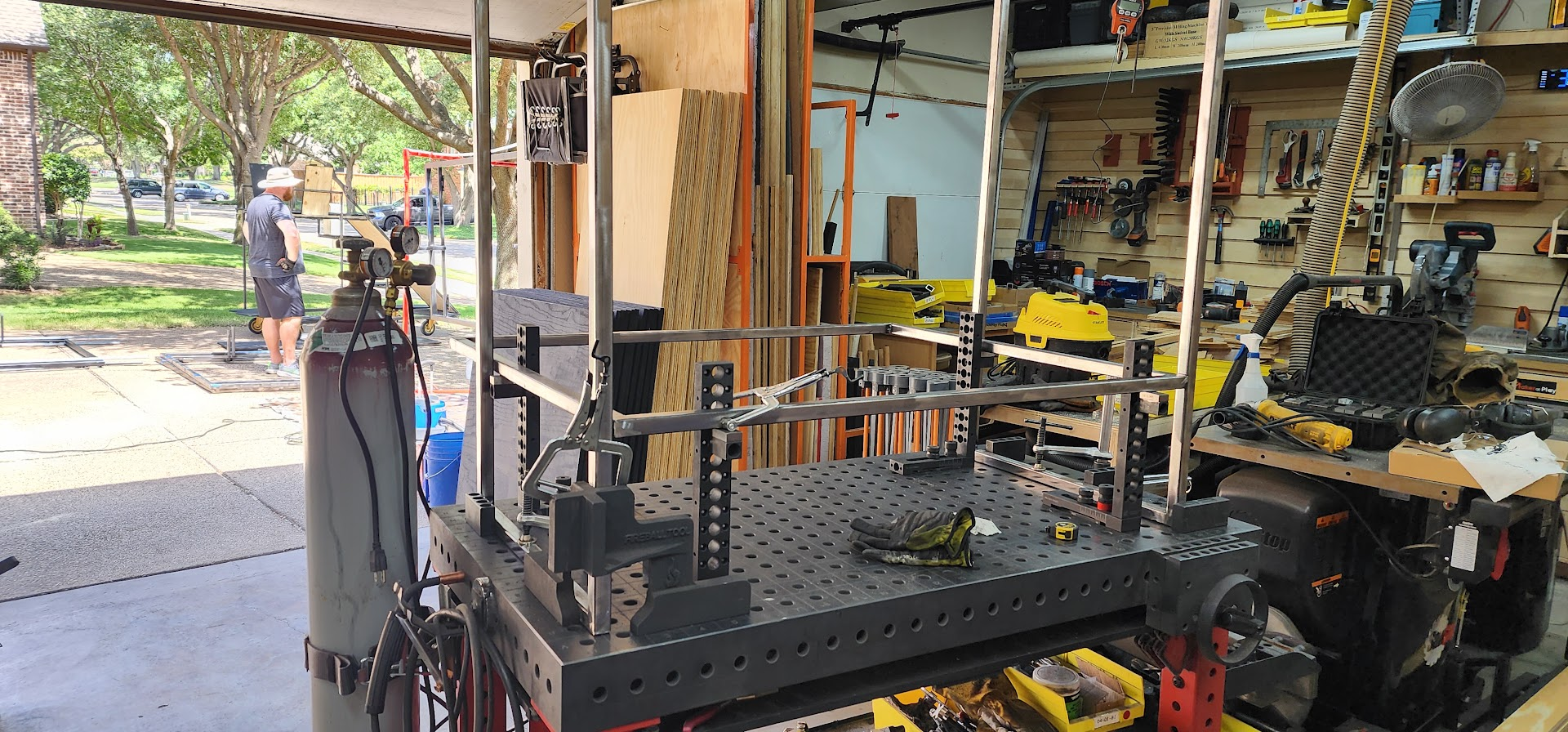
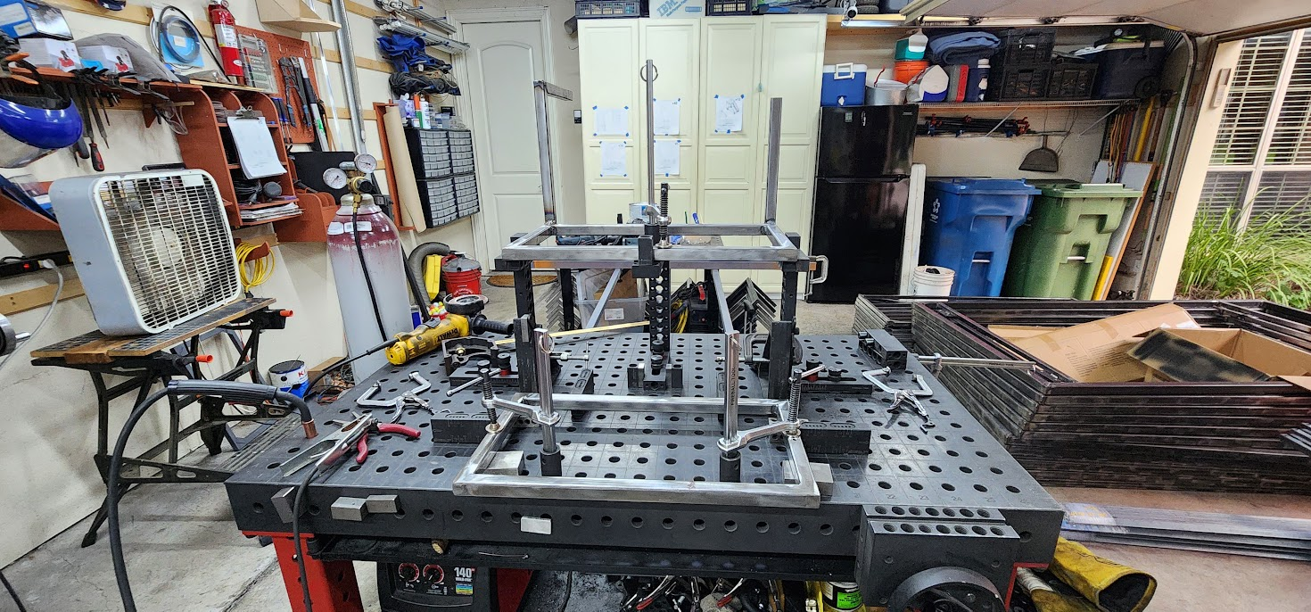
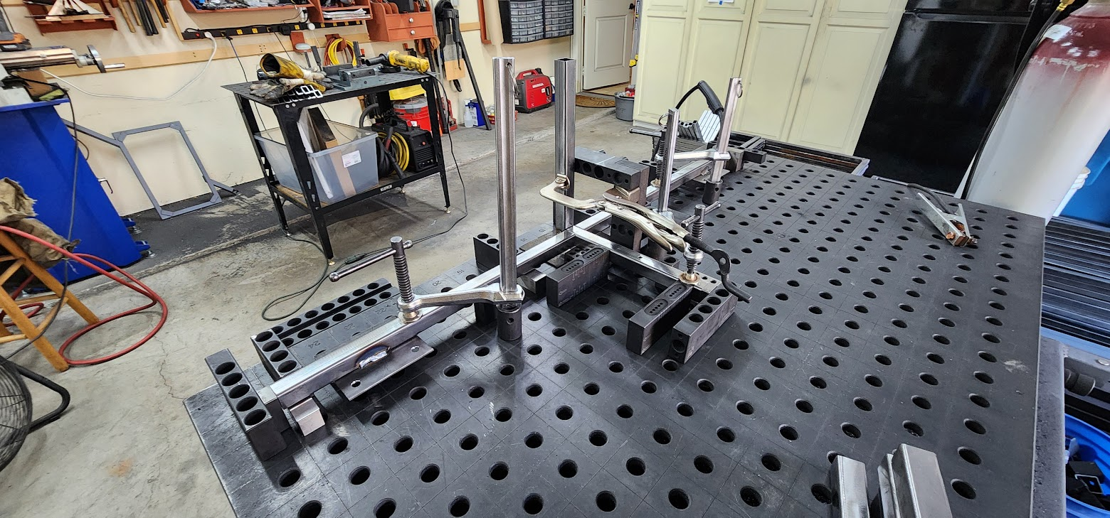
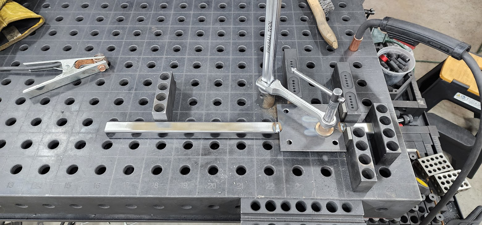
A few weeks ago, I purchased a pair of 13-inch Extension Blocks for my Fireball welding table, knowing they would eventually be needed for this stage. They allow me to fixture one step exactly 12 inches above another while keeping everything square and repeatable.

After building the prototype, I knew I wanted to approach this assembly differently. The new fixture is a significant improvement over the method I used on the prototype, giving me much better control over the alignment of the steps during welding.

Even though I had already worked out the fixture design in CAD, getting everything set up on the welding table still took some time. There was a fair amount of adjusting before I had the extension blocks, fixtures, and clamps positioned so the two vertical supports between the steps could be securely held for welding.

Once the fixture was dialed in, I ground the welds on several of the individual step assemblies to prepare them for final assembly, then welded together the first three-step staircase.

It's always satisfying when a fixture goes from being an idea in CAD to something that actually works as intended.

By the end of the day, the first three-step subassembly was complete. With the process now proven, I expect it will take a few more evenings this week to work through the remaining eleven stair assemblies.

Slowly but surely, twelve staircase props are starting to emerge from what was just a pile of steel a few weeks ago.

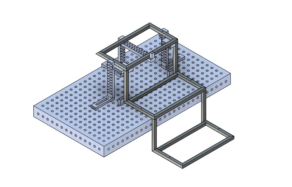
CAD rendering of three-step stair fixture on Fireball welding table

Open on YouTube

Thursday, July 2, 2026

July 2, 2026 – Back to Welding

After experimenting with paint last night, it was back to welding this evening.

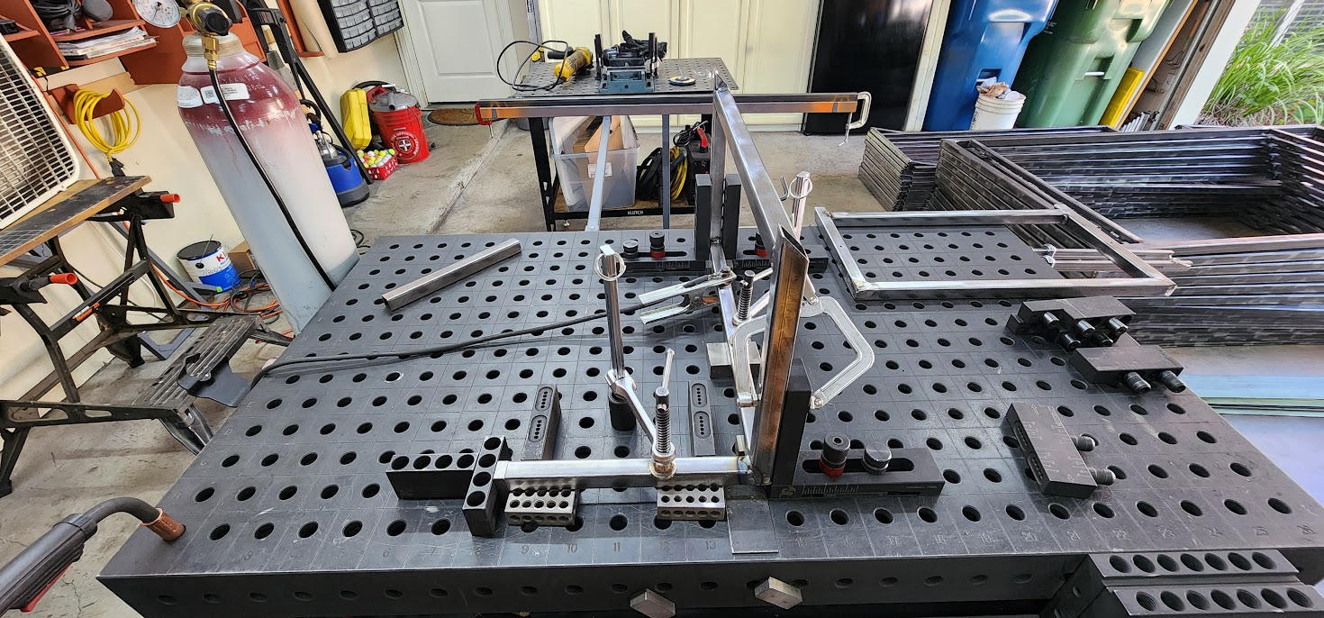
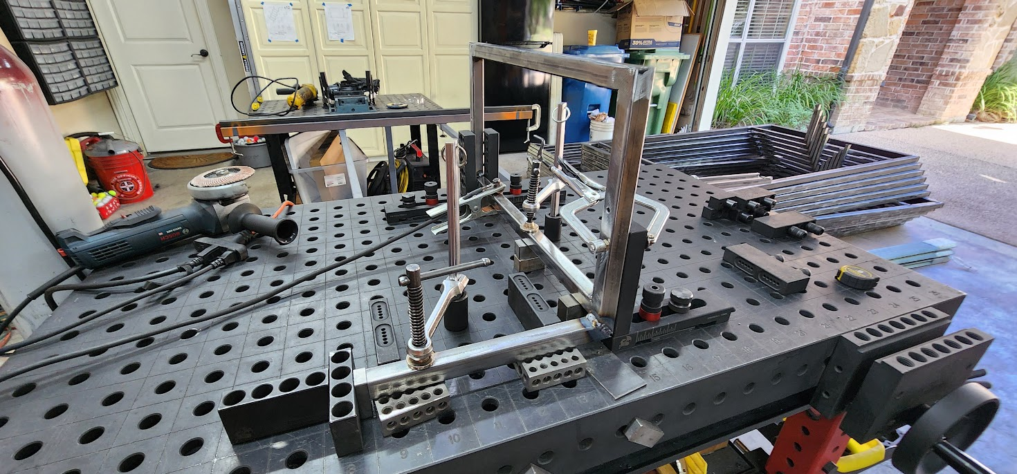
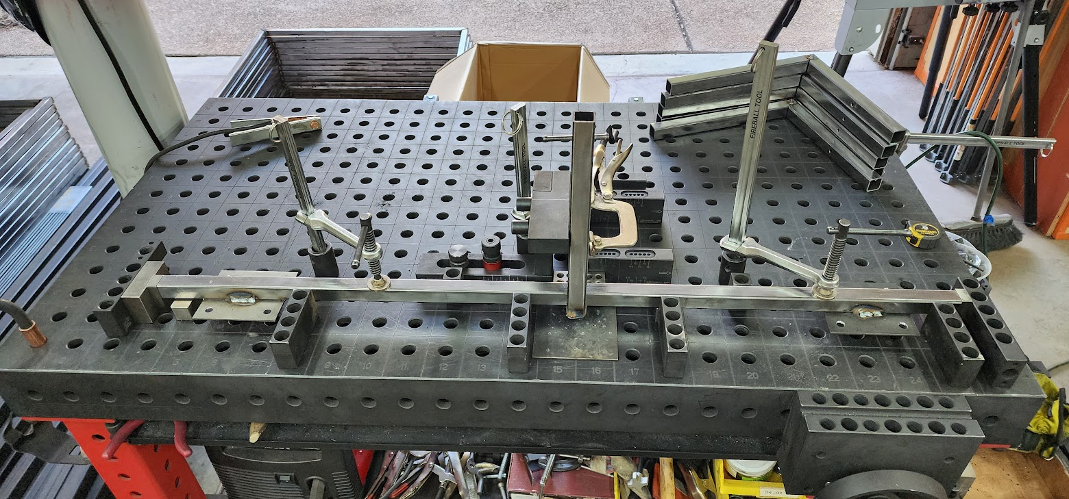
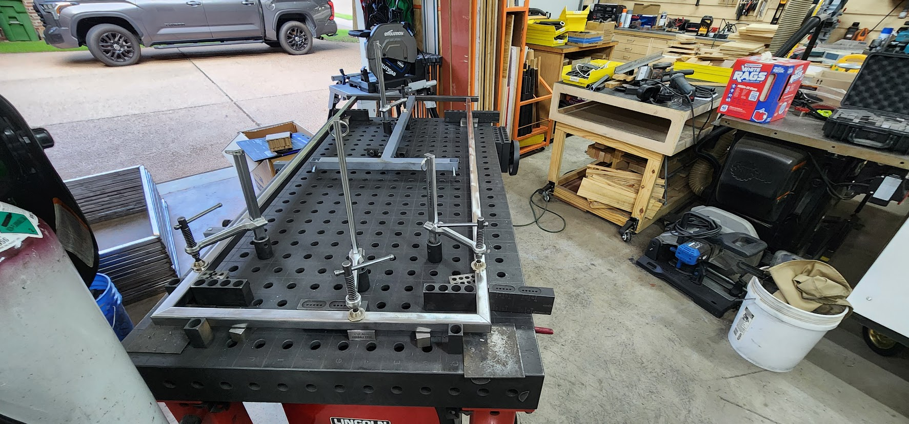
Tonight's goal was to continue building the top step assemblies. After spending some time grinding the welds on the previously completed pieces, I fixtured up another support for the top step and welded together six more assemblies.

At this point, the process is becoming nicely repeatable. That's one of the rewards of spending time designing good fixtures. Once everything is dialed in, the focus shifts from figuring out how to build the part to simply building it accurately over and over again.

Before calling it a night, I assembled the final fixture needed for the remaining top step welds. That should make Sunday's shop session much more productive. Rather than spending time setting up, I can jump right into welding the last of the top step assemblies.

Once those are complete, it will finally be time to move on to assembling the full three-step staircase sections.

It's exciting to be approaching that milestone. Up until now, most of the work has been producing individual subassemblies. Over the next several shop sessions, those parts will begin coming together into recognizable sections of the finished props.

One evening at a time, the pile of parts continues to become a set of staircase props.

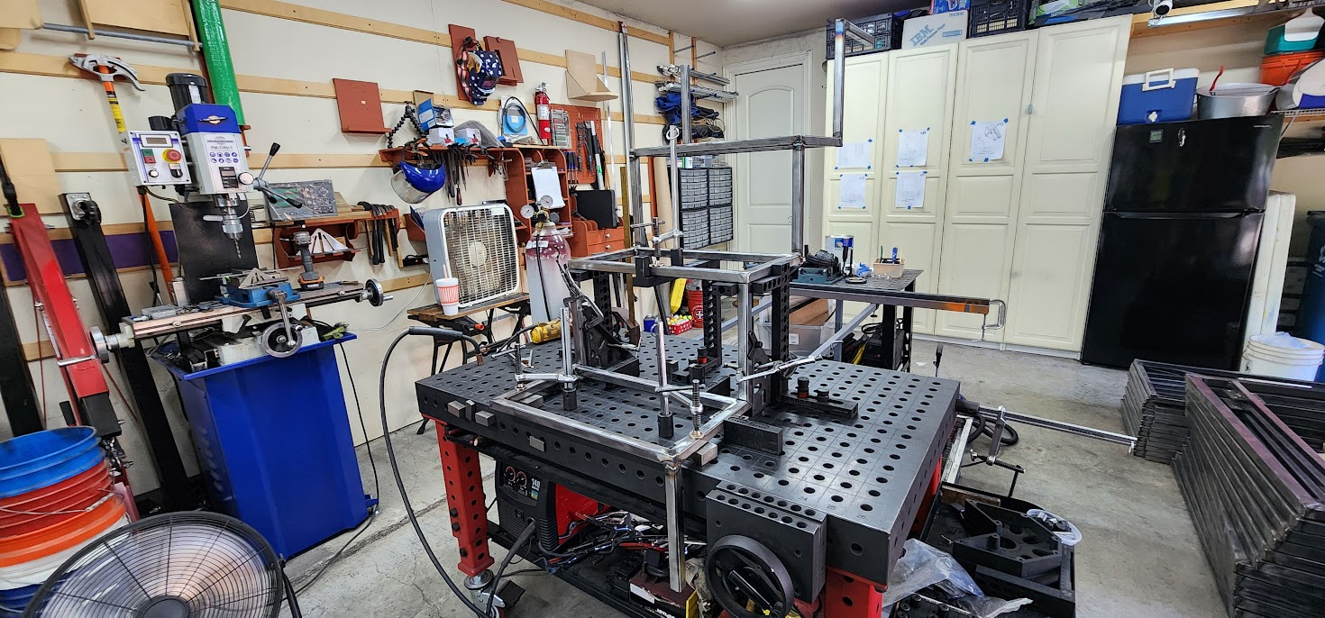
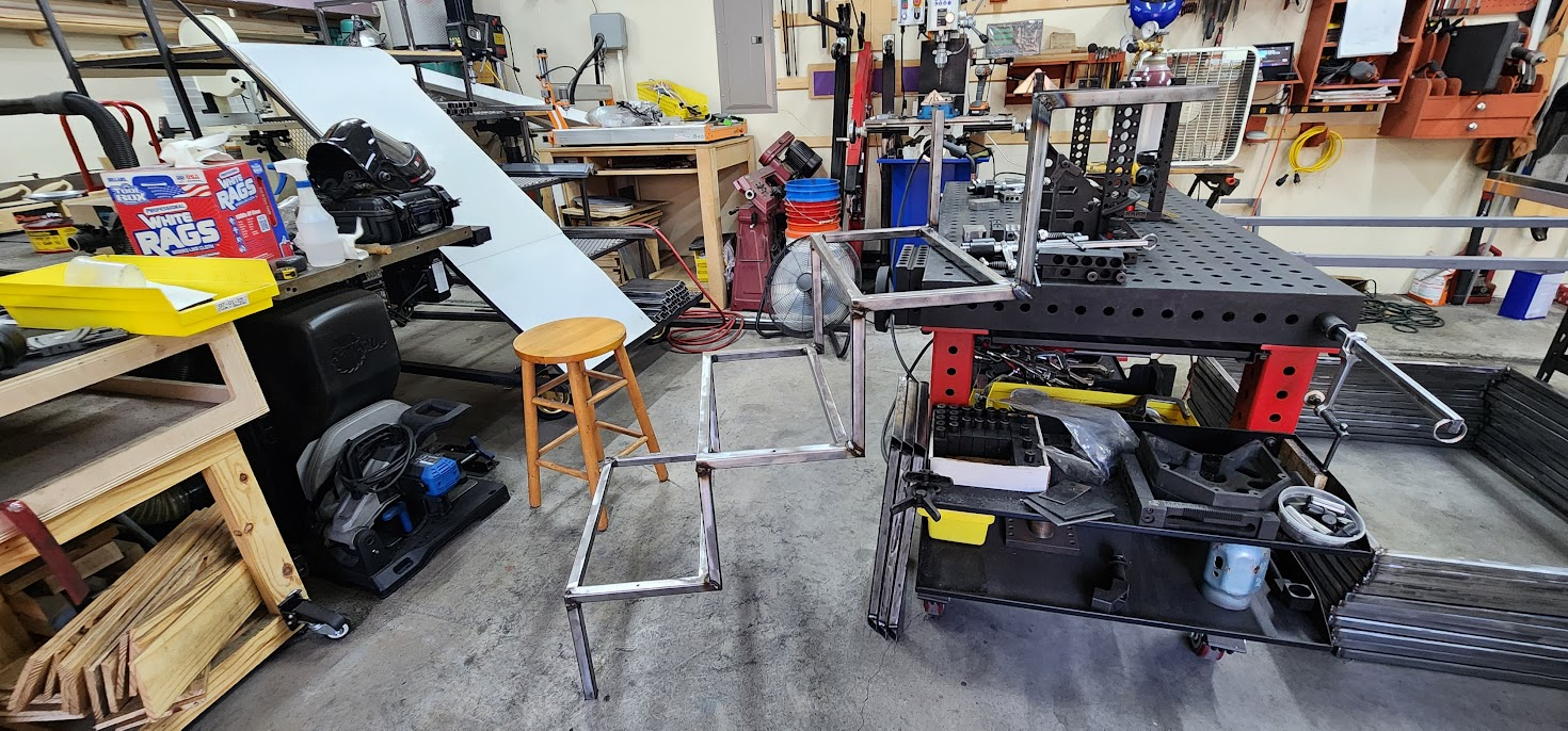
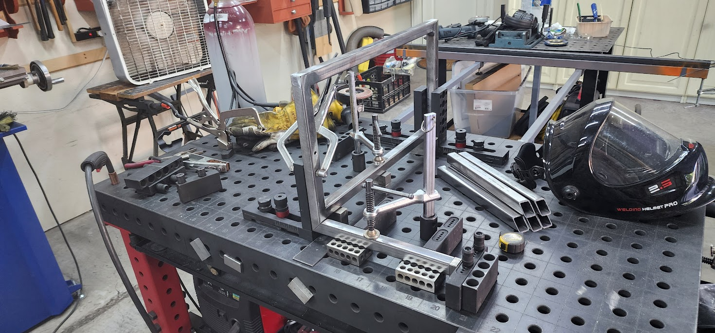
Top step assembly fixtured on Fireball welding table with clamps and welding gear

Open on YouTube

Wednesday, July 1, 2026

July 1, 2026 – Preparing for Paint

The first parent prop workday is coming up on Saturday, July 11, and one of the biggest jobs will be painting.

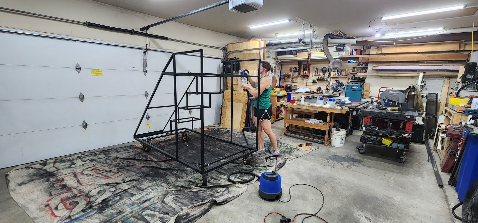
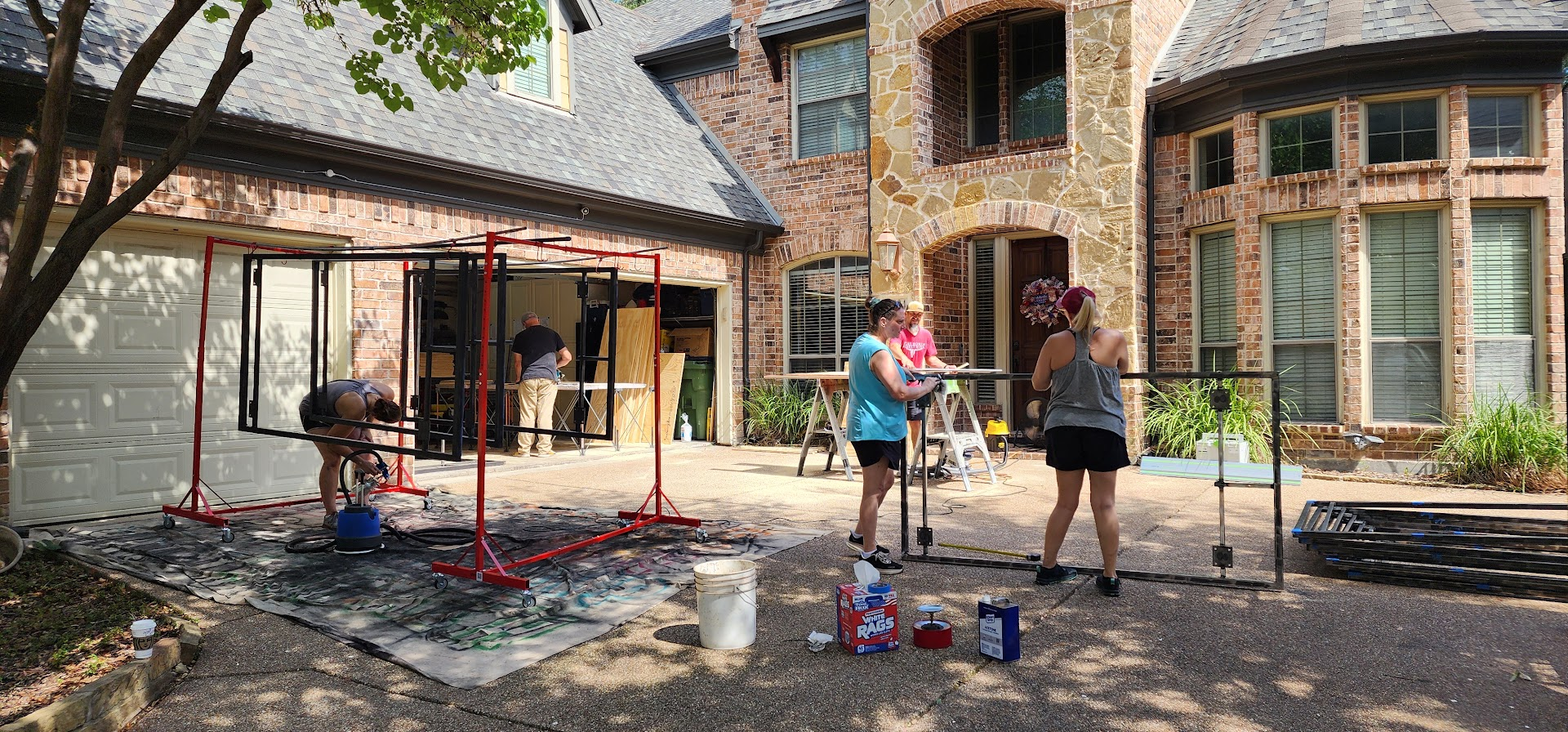
Rather than waiting until the props are fully assembled, I'm planning to paint many of the subassemblies first. My hope is that this will make it much easier to get complete paint coverage, especially in all the tight corners that become difficult to reach once everything is welded together.

In past years, we've painted the metal frames using rattle cans. They work well enough, but when you're painting twelve large props, spray cans become both expensive and time consuming.

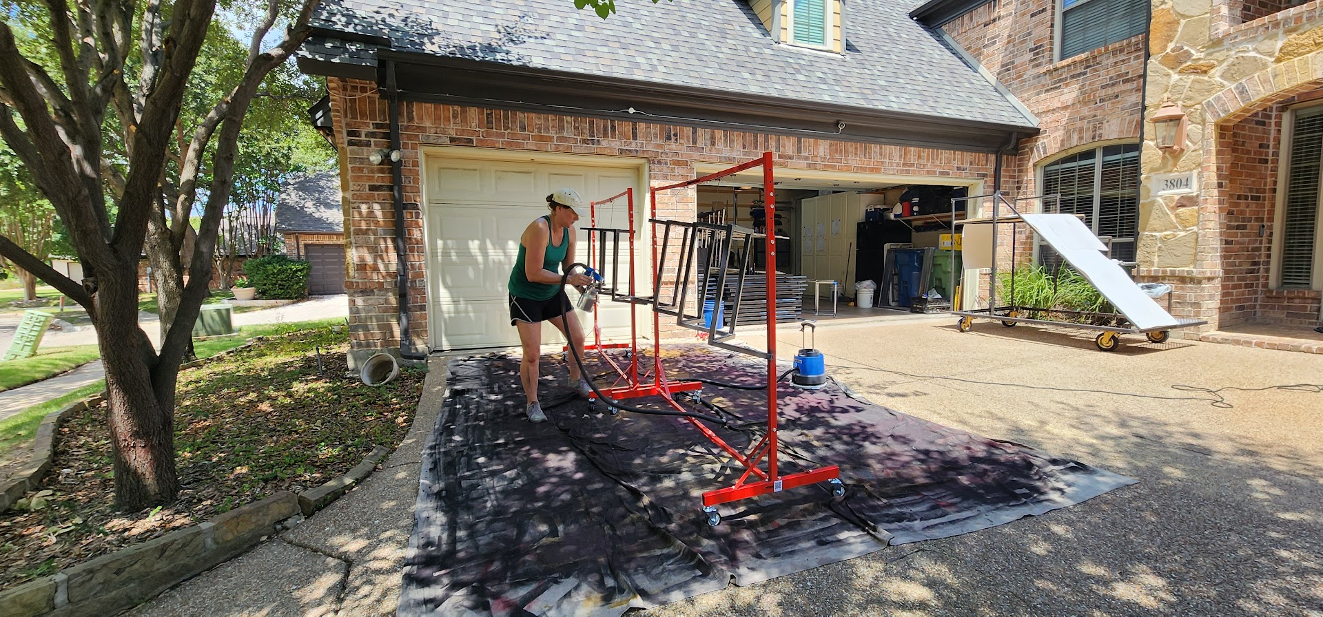
This year, I wanted to try something different.

I picked up a gallon of paint and spent the evening testing it with my HVLP paint sprayer. Fortunately, the results were encouraging. The paint sprayed well, gave good coverage, and should be much more economical than using dozens of spray cans.

Of course, every test uncovers the next problem to solve.

My first attempt at hanging the parts from a single hook wasn't ideal. The pieces swung around too much while spraying, making it harder to get an even coat.

So before the parent workday, I'll be building some kind of paint rack that allows multiple parts to hang securely while keeping them from moving around too much. A little preparation now should make painting day go much smoother for everyone.

Just another example of how building the props isn't the only project. Sometimes you have to build the tools that help you build the props.

Open on YouTube

Tuesday, June 30, 2026

June 30, 2026 – Every Project Has a Mistake

Mistakes were made.

One thing I've learned over the years is that every project has at least one "well...that wasn't supposed to happen" moment. Today was that day.

Friday night I got into a good rhythm welding the lower step assemblies and finished all twelve of them. There was just one problem.

They weren't all supposed to be the same.

Because these props are built as six mirrored pairs, half of the stair assemblies need to be left-handed and the other half right-handed. Somewhere along the way, I lost sight of that and happily built all twelve identically.

The interesting part is that the original Fusion 360 design didn't have this problem.

Originally, the support in question was going to be welded directly to the base frame. That meant the only mirrored assemblies were the base frames themselves. But during the production planning, I called an audible and decided it would make final assembly easier if I welded that support onto the lower step first instead.

It was a good manufacturing decision.

Unfortunately, I forgot that changing the assembly sequence also changed which parts needed to be mirrored.

So the first task of today's shop session wasn't building props.

It was fixing yesterday's mistake.

Out came the cutoff wheel.

I removed the misplaced support from six of the lower step assemblies. Since cutting them off shortened the supports, I also had to fabricate six replacement pieces before welding everything back together in the correct orientation.

Thankfully, it was a mistake that cost me only time.

With those assemblies corrected, I was able to move on and weld the support onto the top step assemblies. This time, I made absolutely sure to keep the left-hand and right-hand versions separated throughout the entire process.

As frustrating as mistakes can be, they're part of building things.

I'd much rather discover an error like this now, while working on subassemblies in the shop, than after the props are fully assembled or, even worse, during rehearsals.

By the end of the evening, the mistake had been corrected, the project was back on track, and the production line was moving again.

Sometimes progress means building something new.

Sometimes progress means admitting you built something wrong and taking the time to make it right.

Open on YouTube

Saturday, June 27, 2026

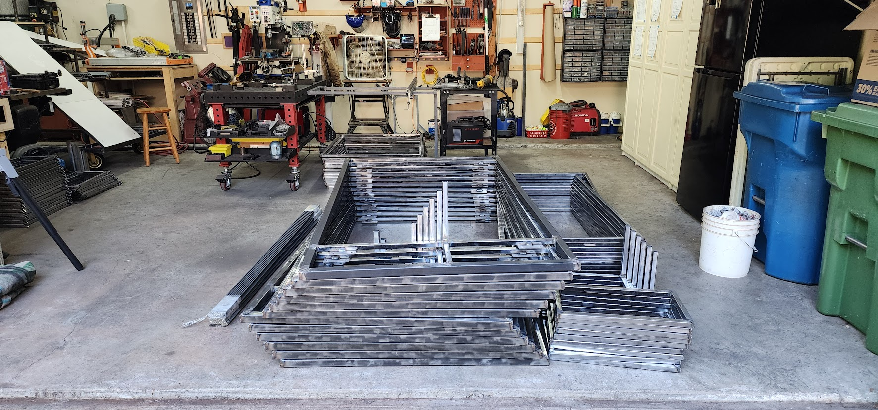
June 27, 2026 – Twelve Base Frames Complete

Today was a very productive Saturday in the Maker At Play props workshop and a major milestone in the project.

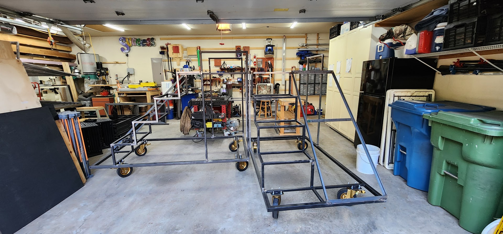
The goal for today was to complete all twelve base frames, the largest subassembly that will be built on the welding table. Every prop starts with this foundation, so getting all twelve completed represents a significant step toward full production.

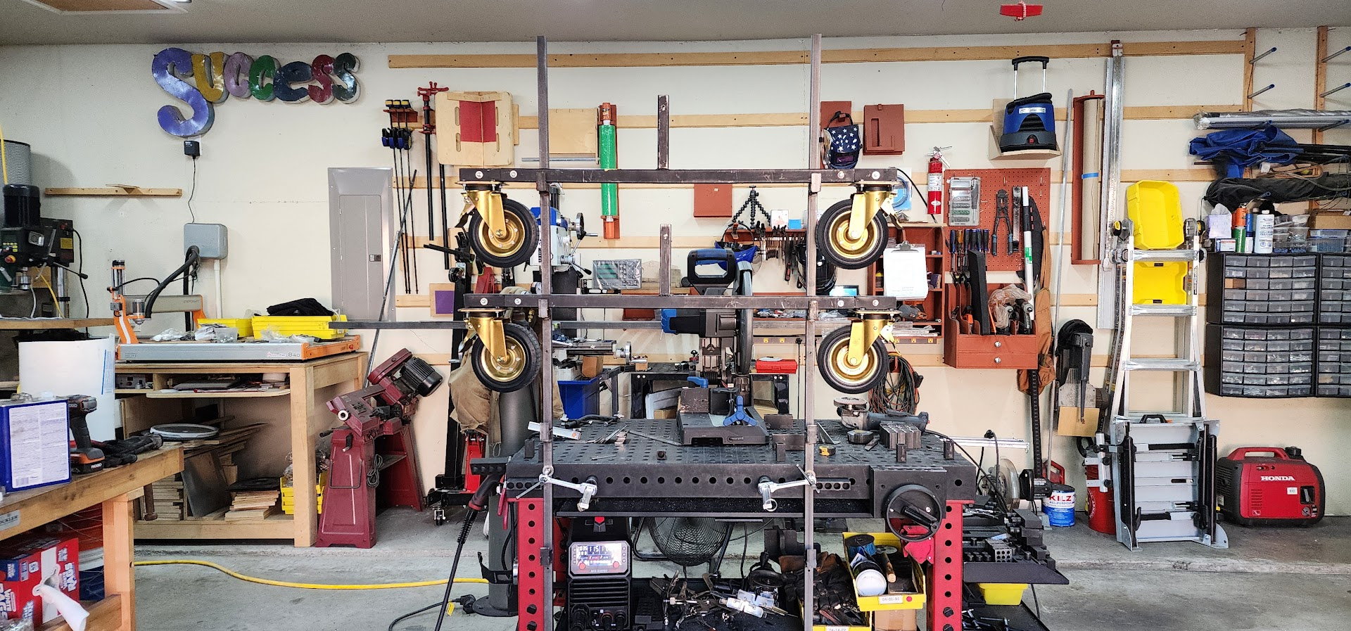
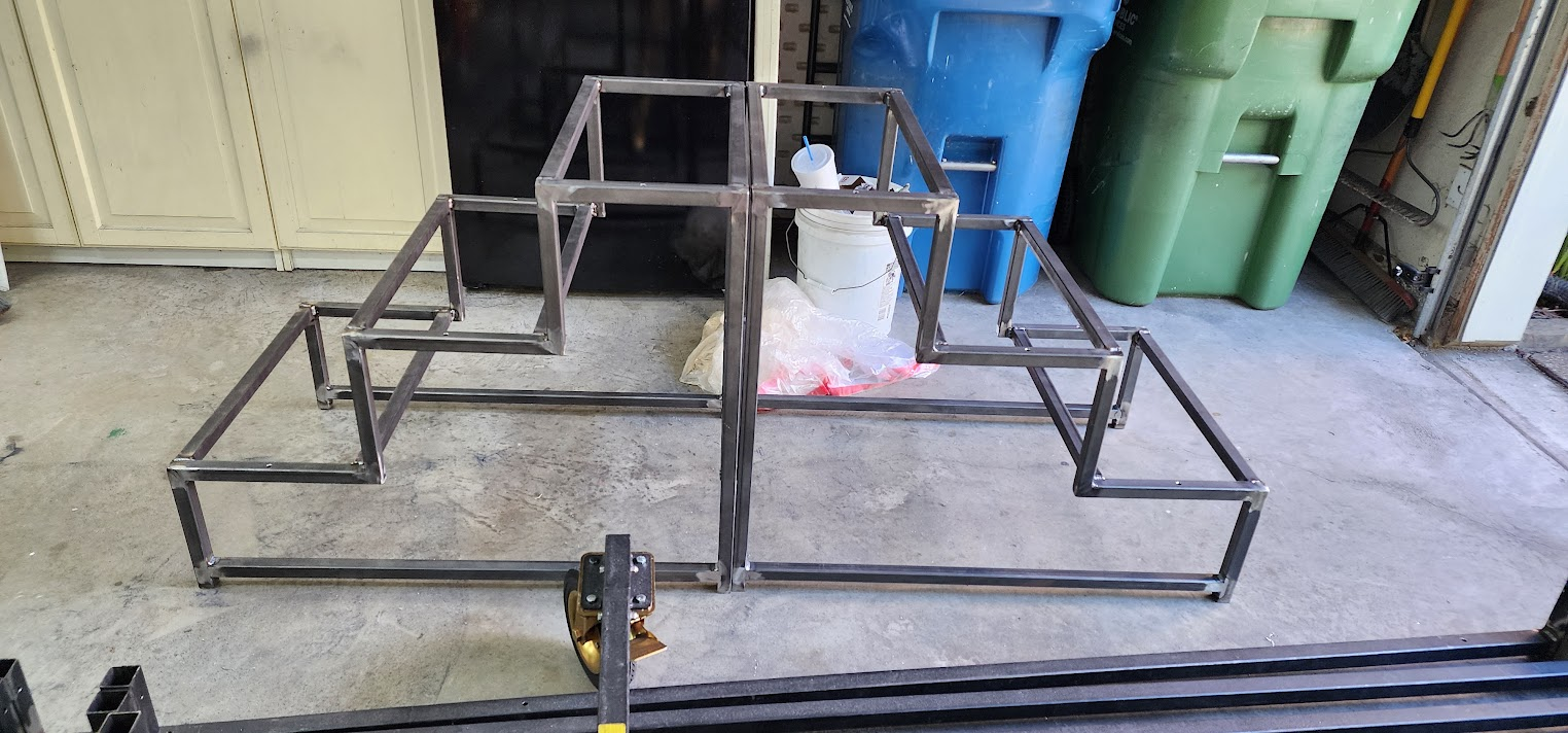
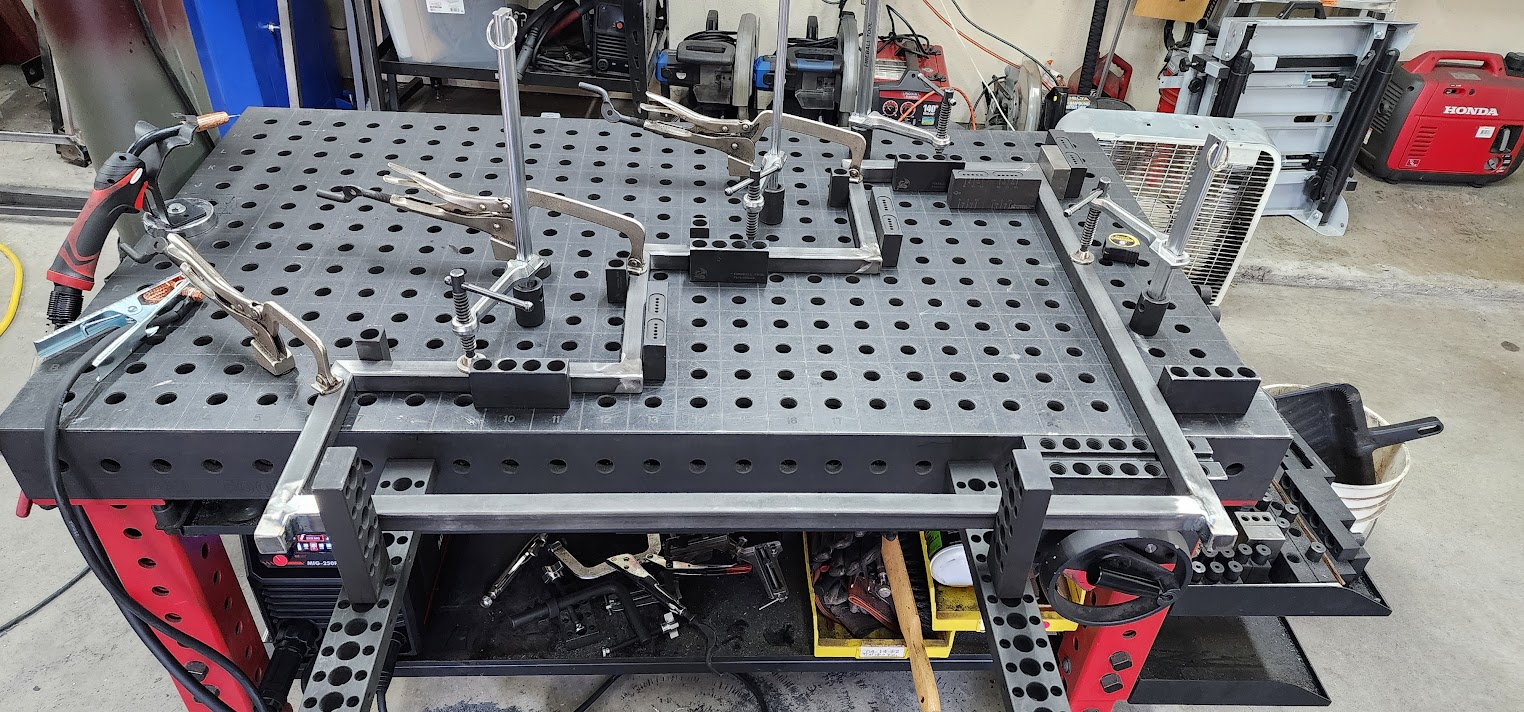
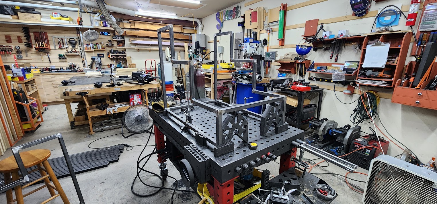
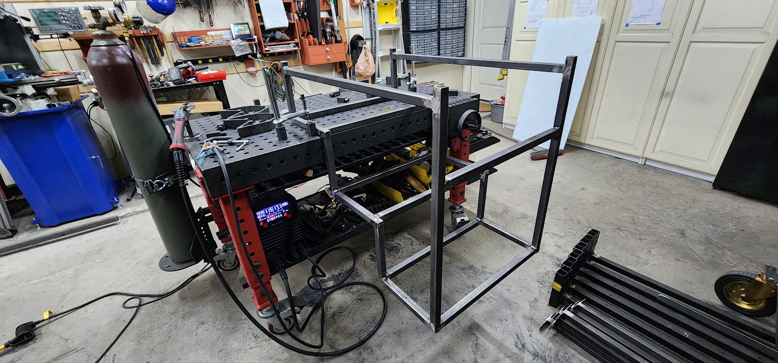
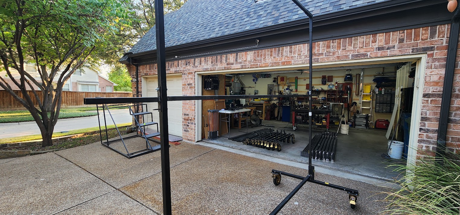
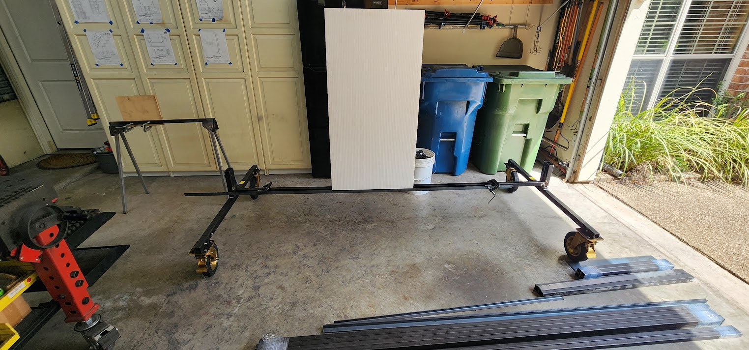
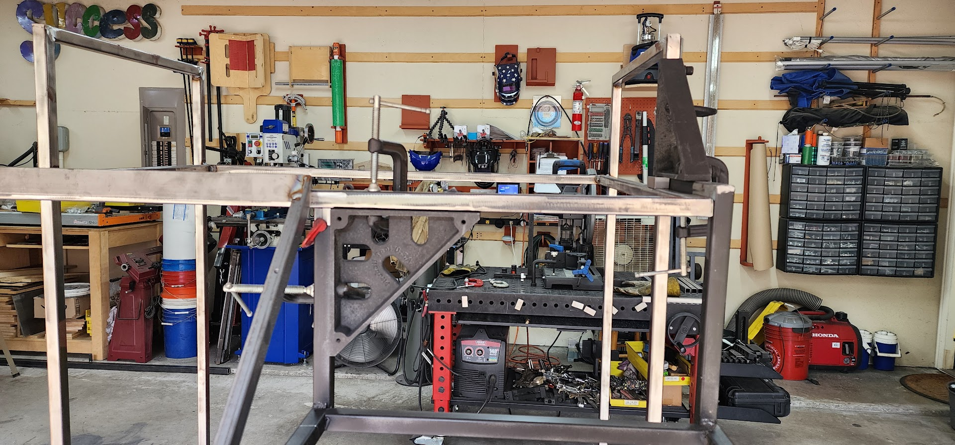
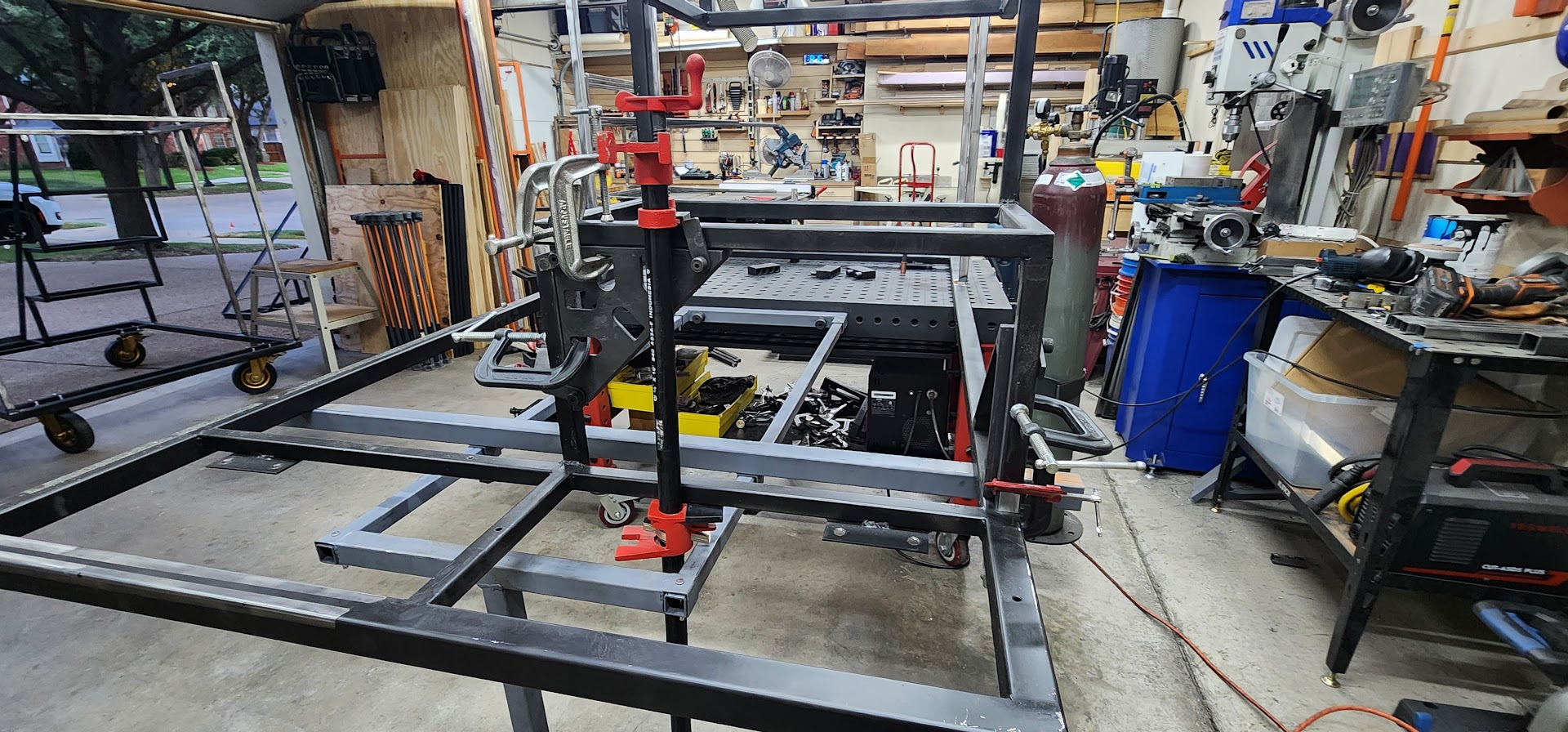
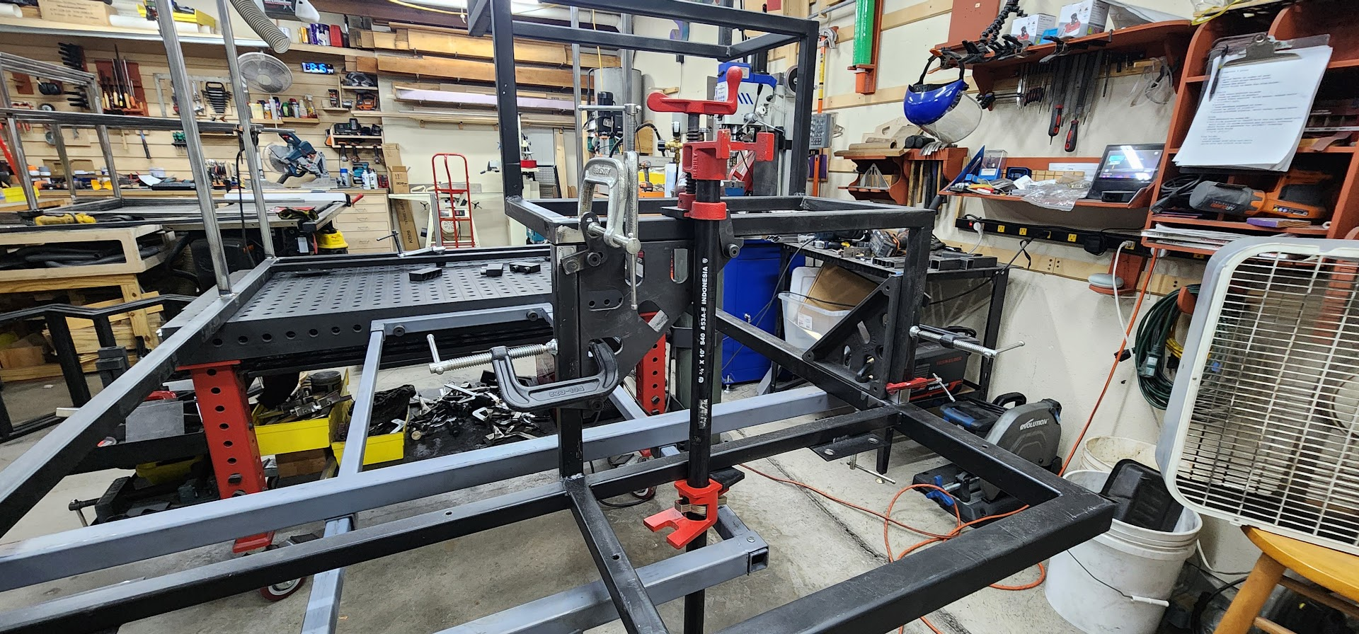
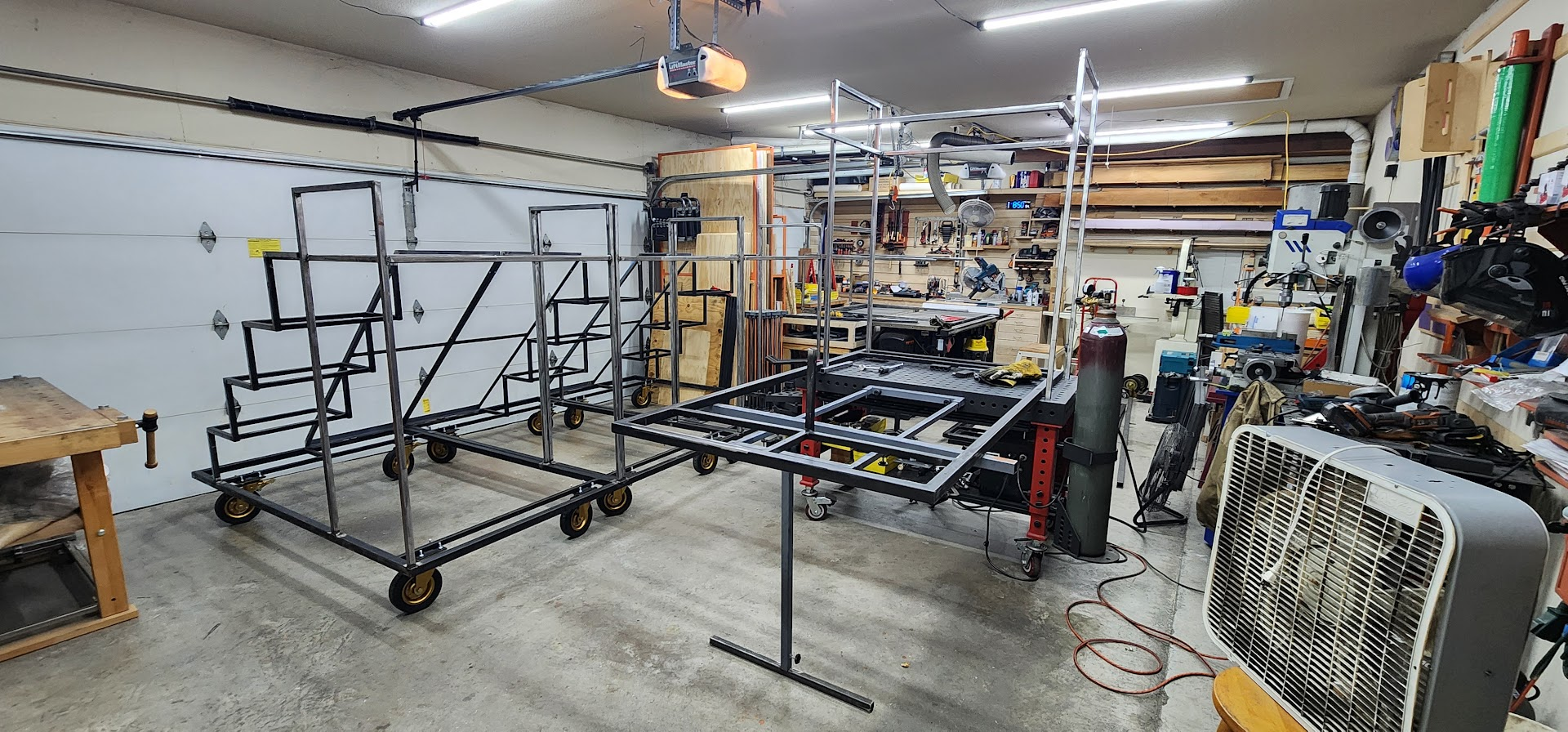
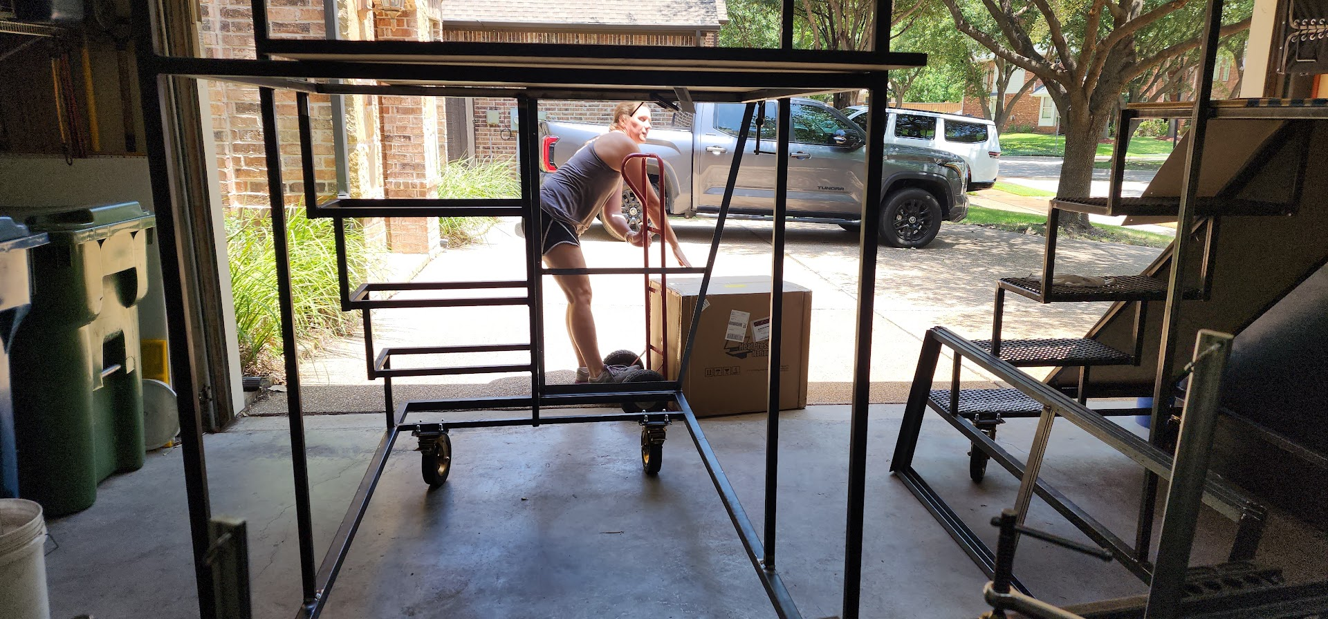
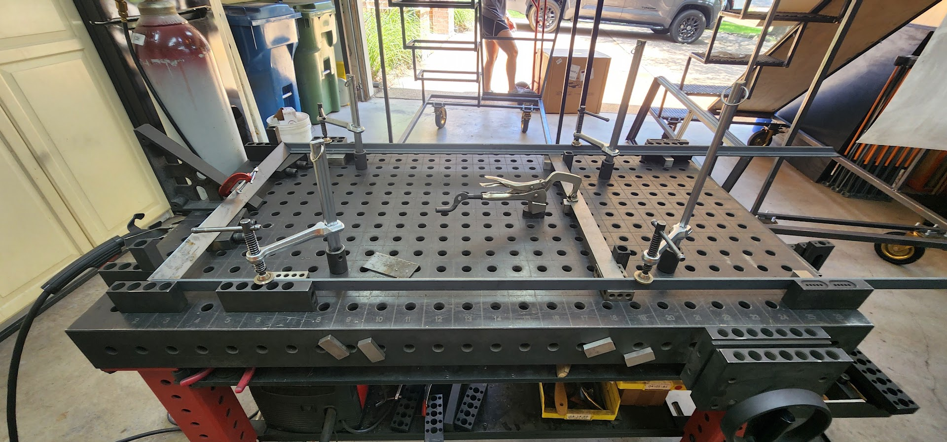
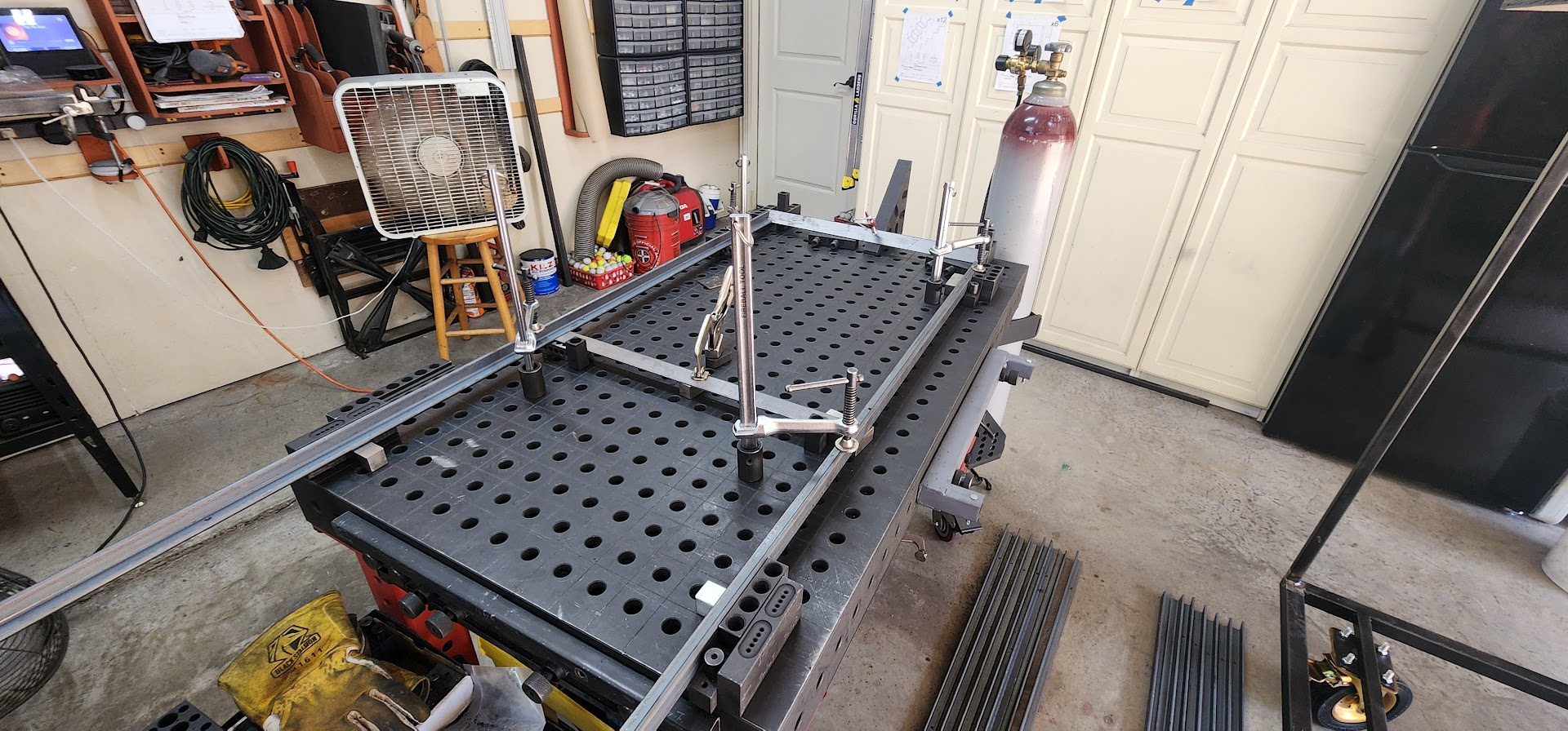
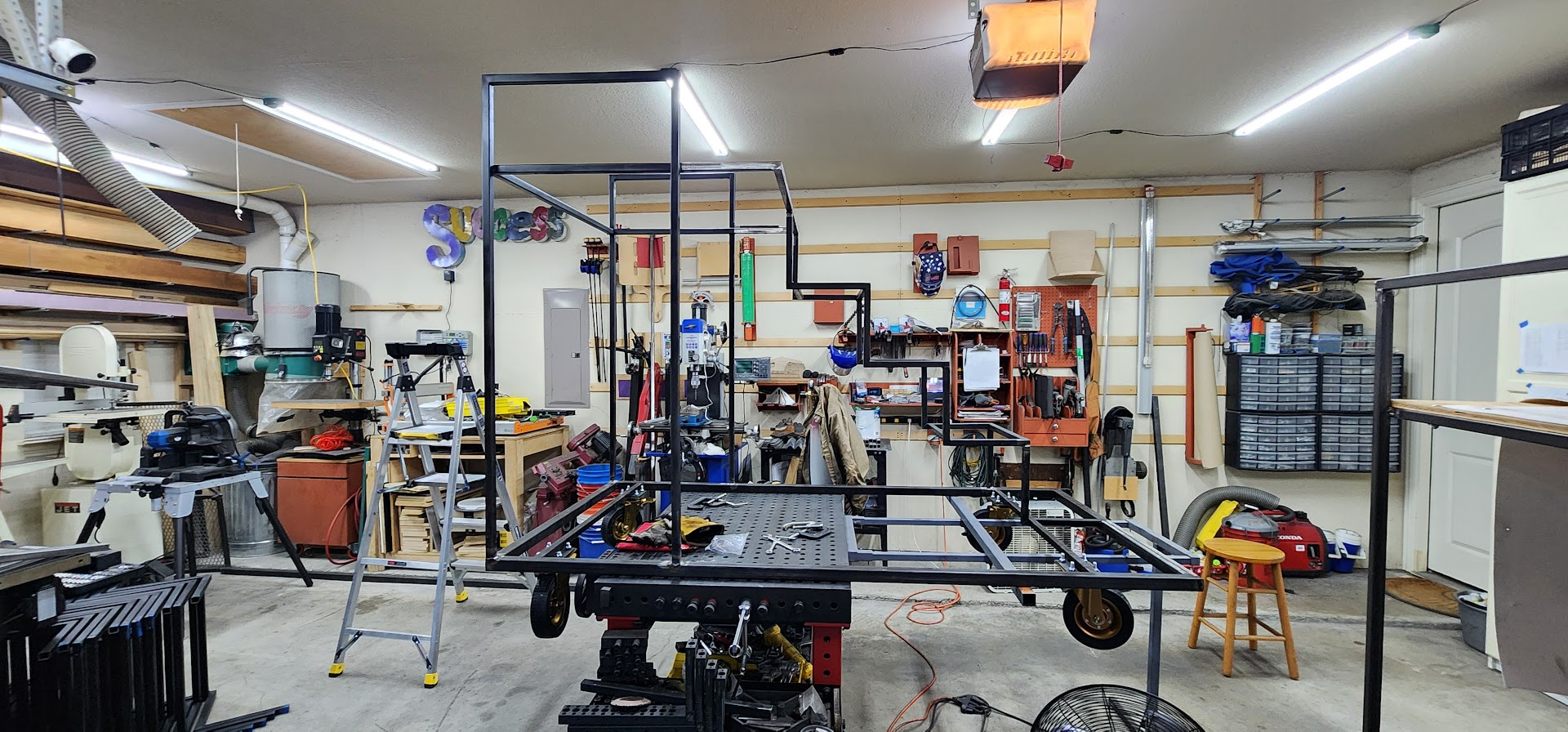
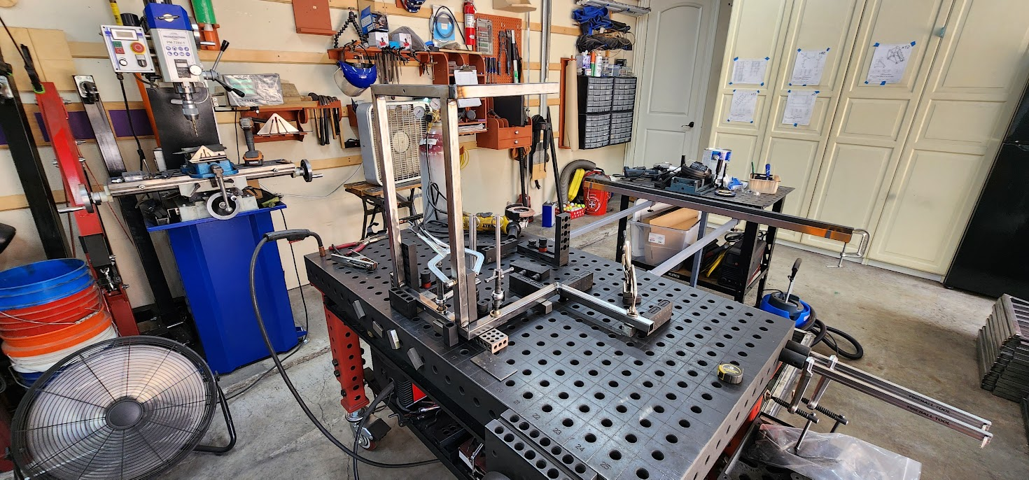
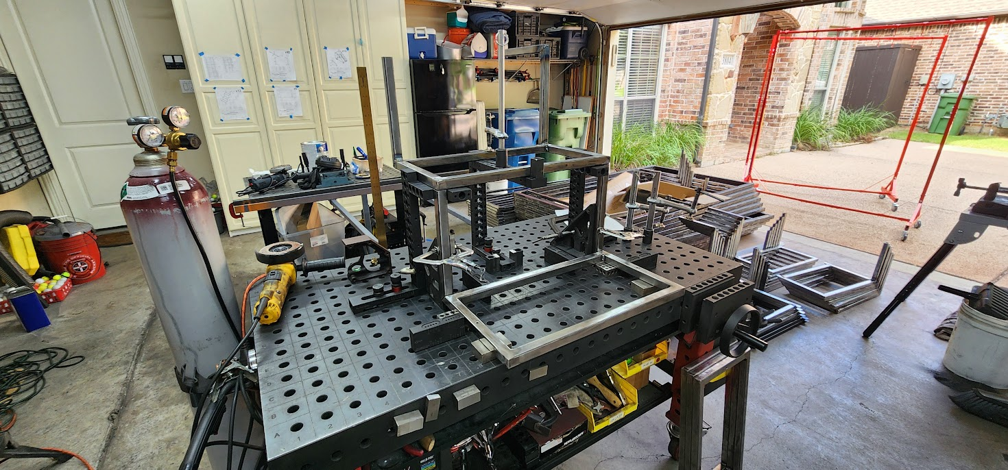
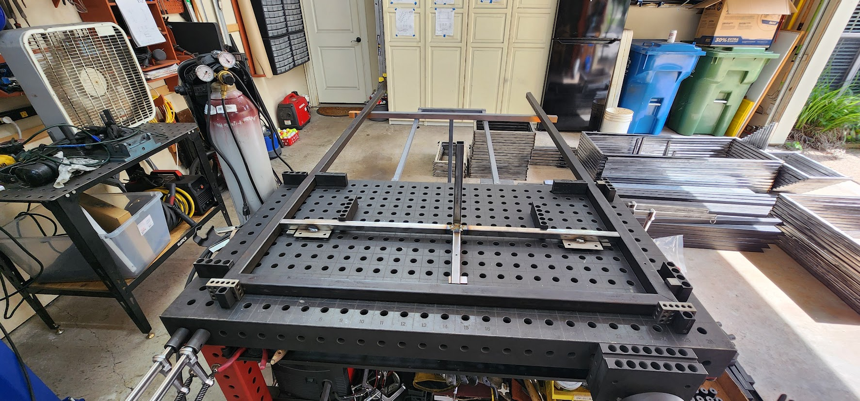
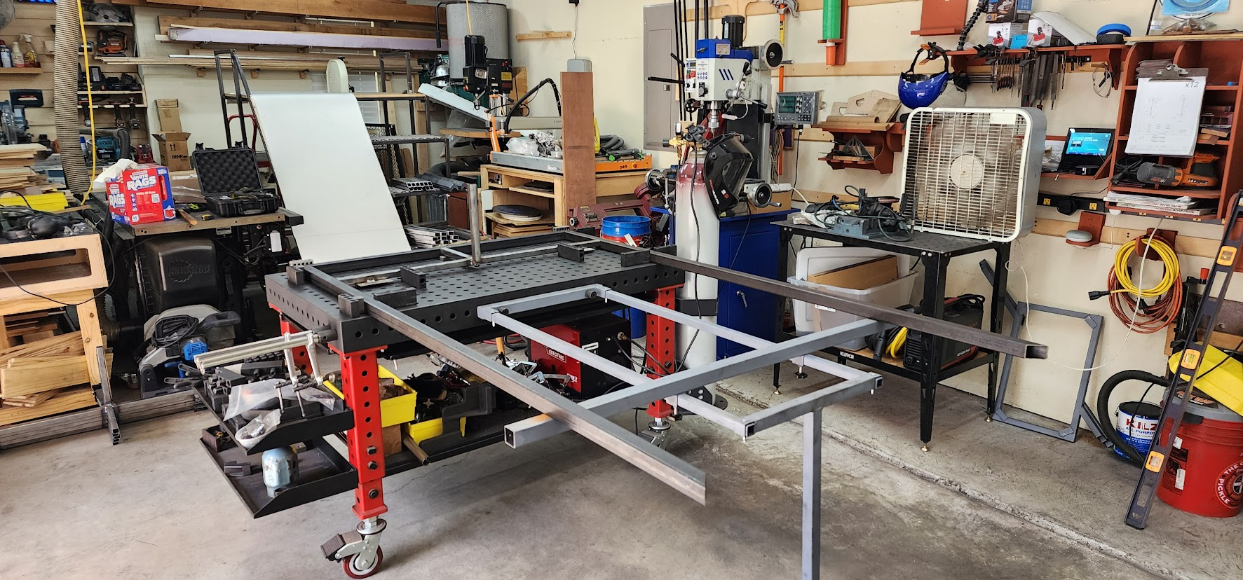
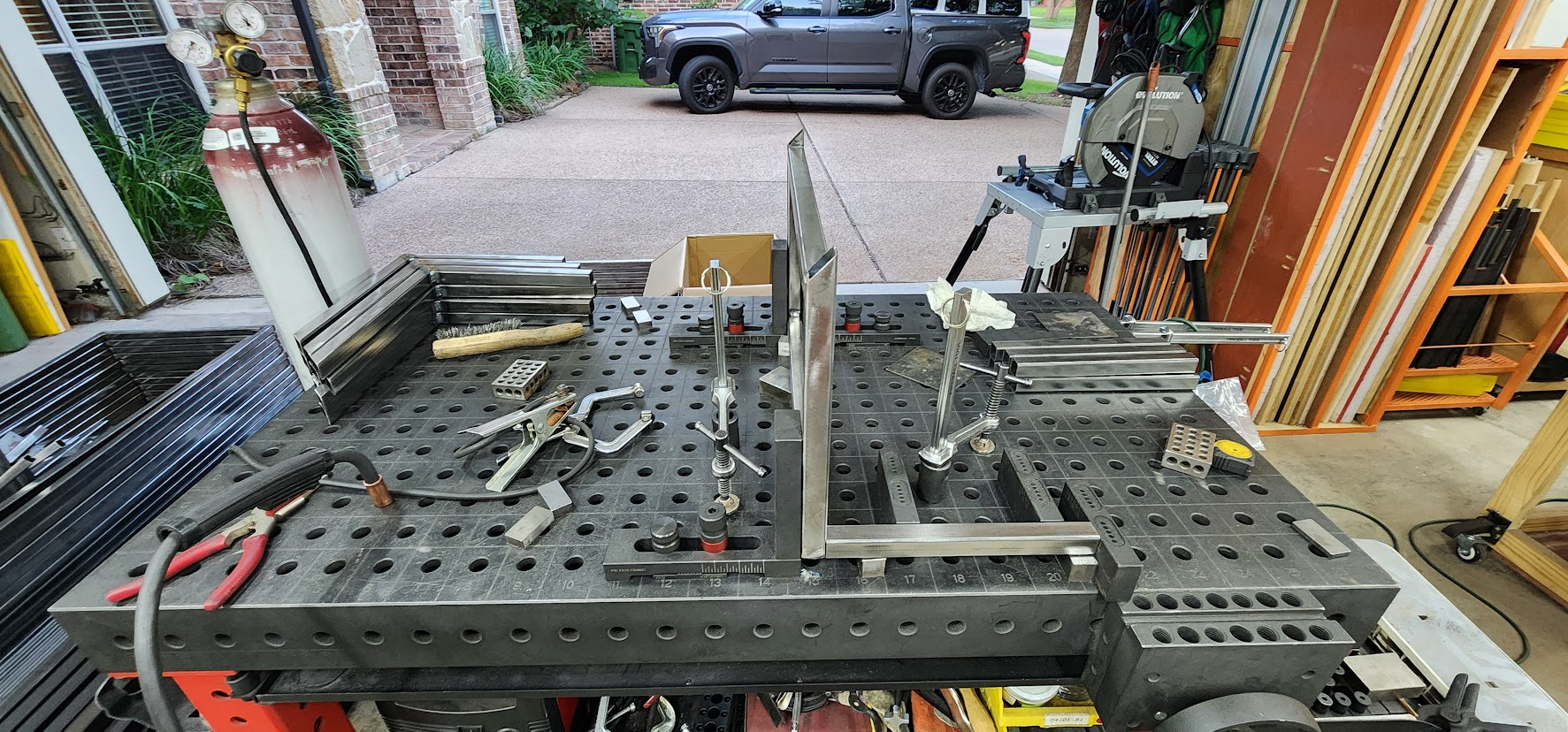
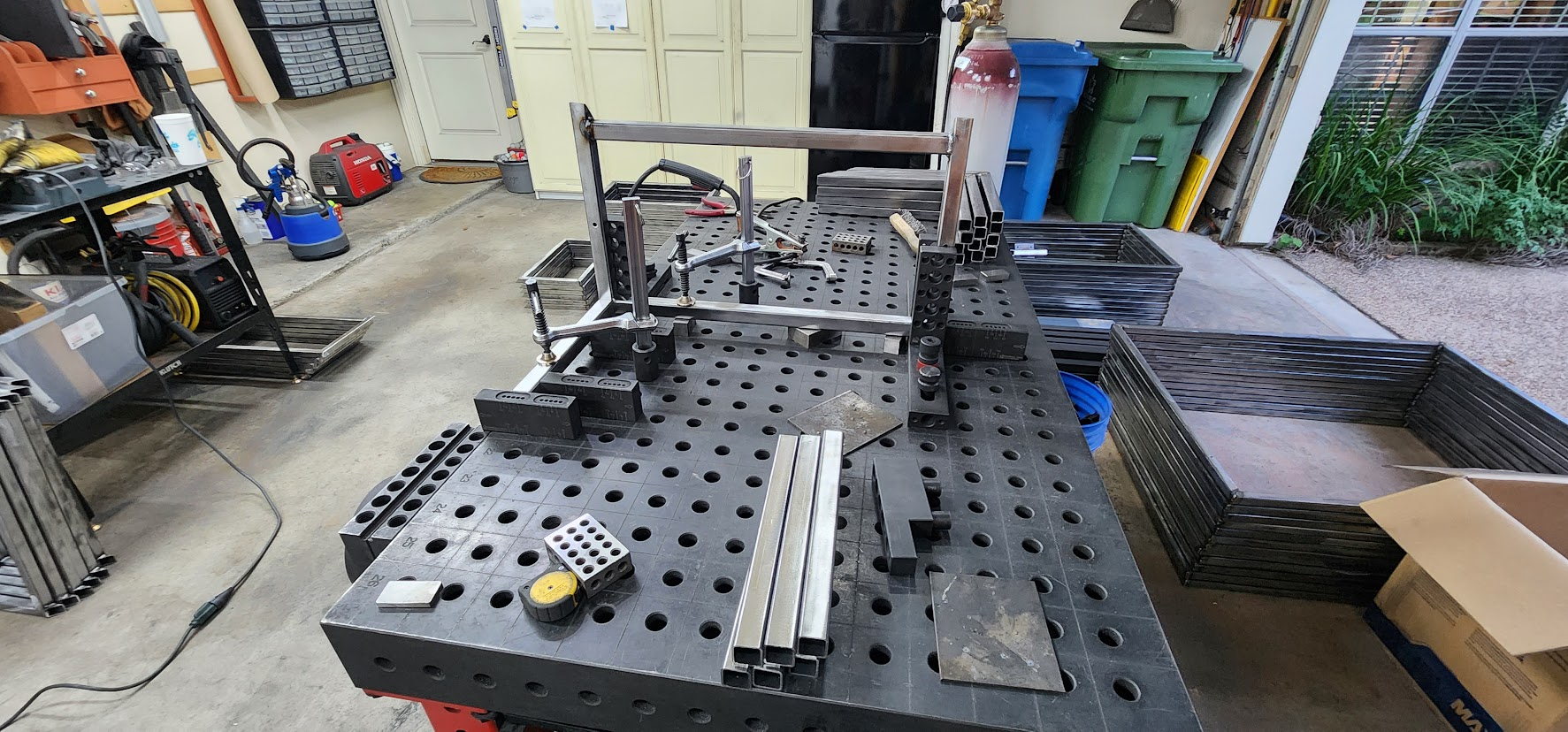
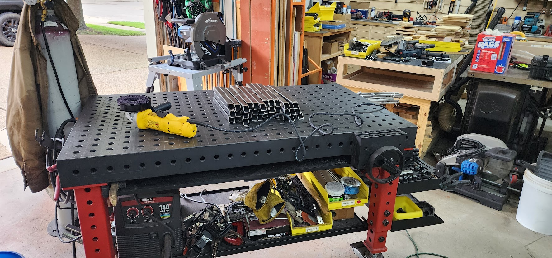
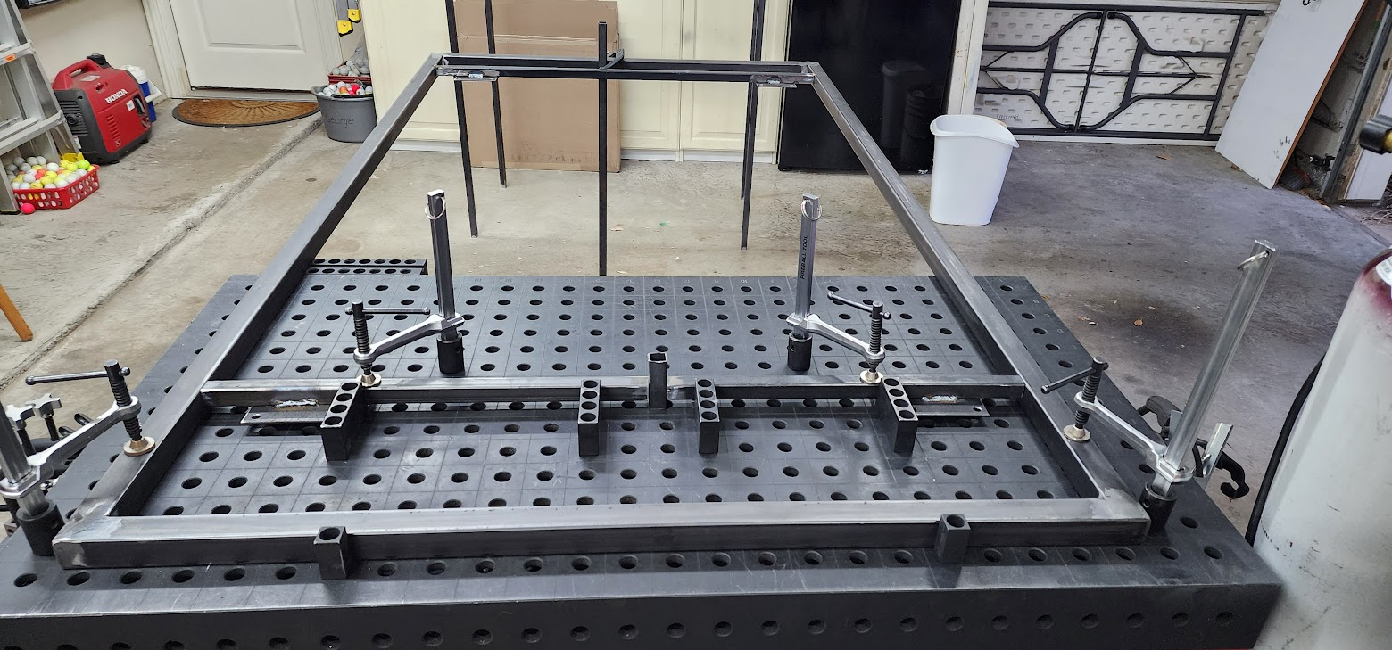
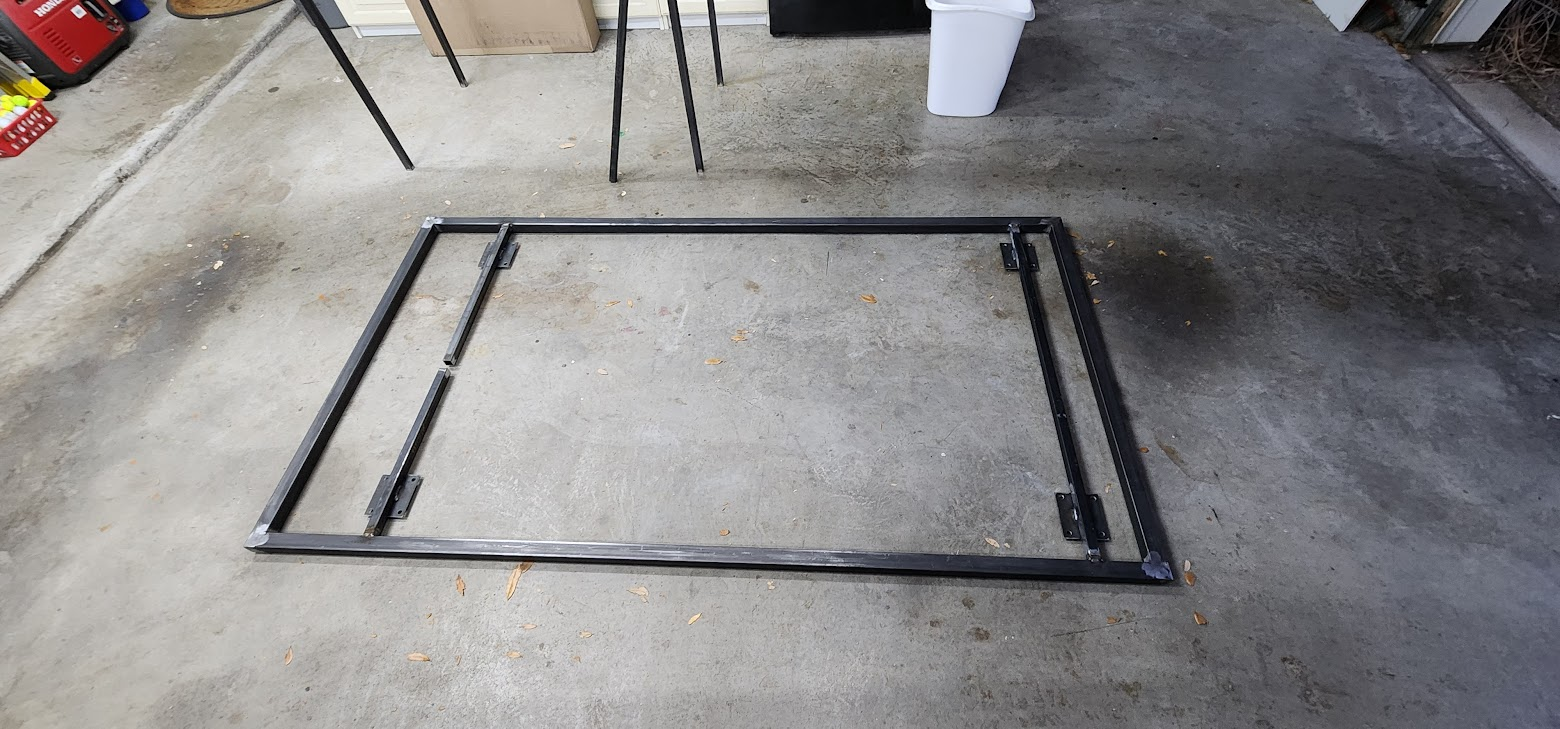
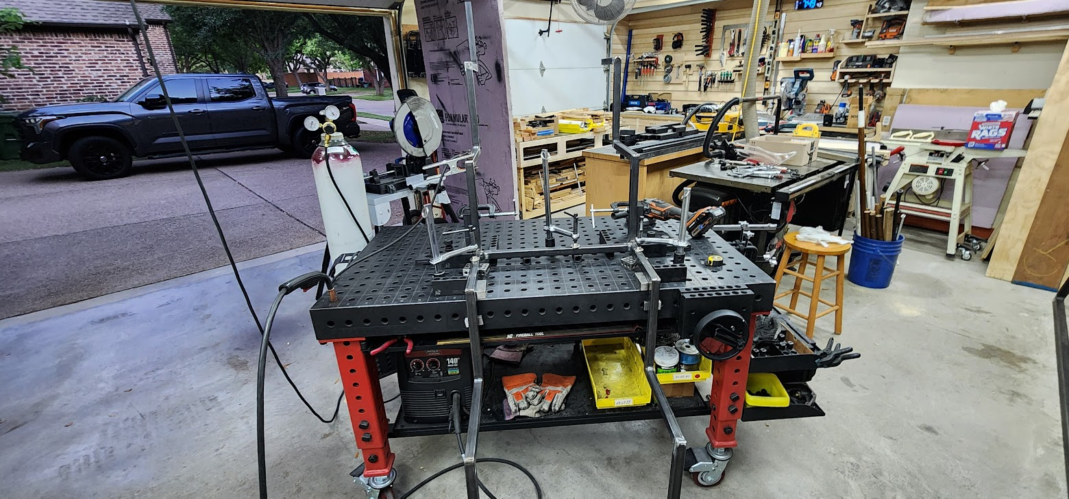
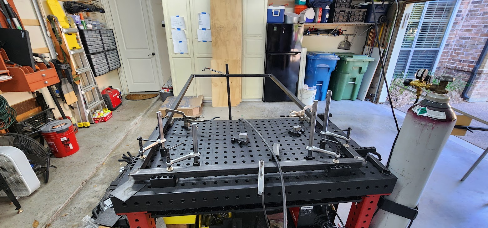
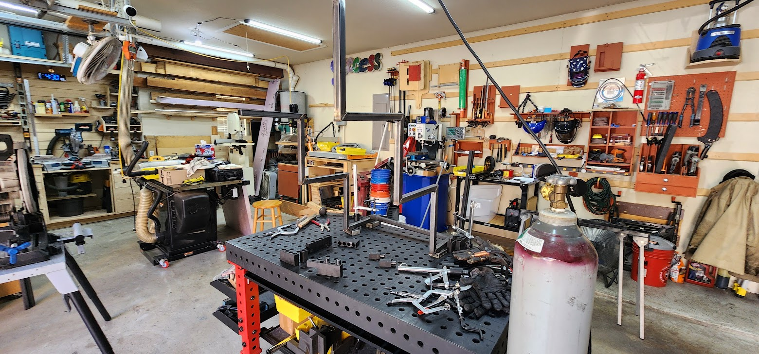
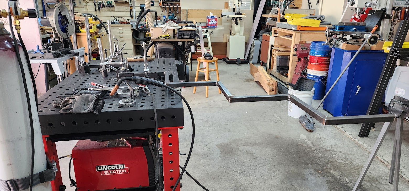
After building the prototype, I realized my Fireball welding table needed a little help. A 4-by-7-foot base frame is much larger than the table itself, so I built an extension from 1-inch square tubing that bolts onto the back of the table. The extension reaches about four feet behind the table and includes a 4½-foot support that slides along the rails while staying perfectly flush with the tabletop. It turned out to be a simple addition that made handling these large assemblies much easier.

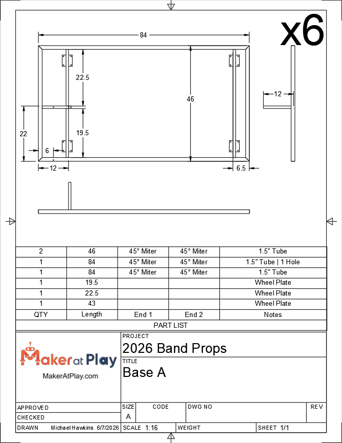
Each base frame is constructed from four pieces of 1½-inch square tubing along with two wheel plate subassemblies. Once welded together, they become the rolling foundation for the entire prop.

One interesting challenge is that not all twelve bases are identical.

The show design calls for mirrored pairs of staircase props. Six props have the stairs on the left side, while the other six have the stairs on the right. That means the wheel plate locations and mounting points have to be mirrored as well so the stair assemblies can be attached correctly later.

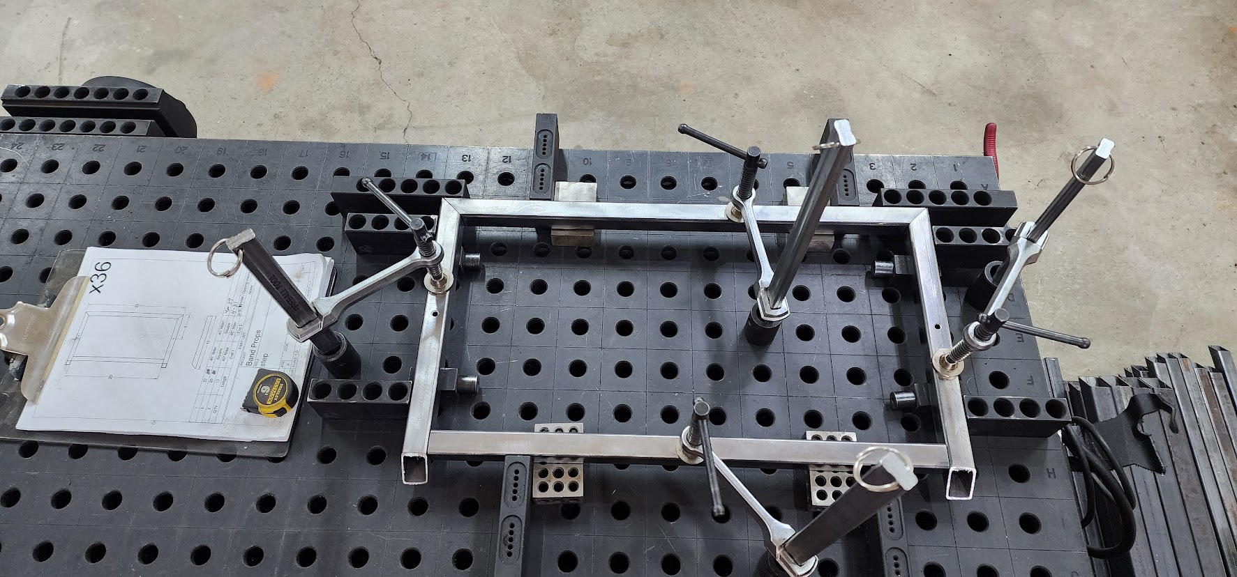
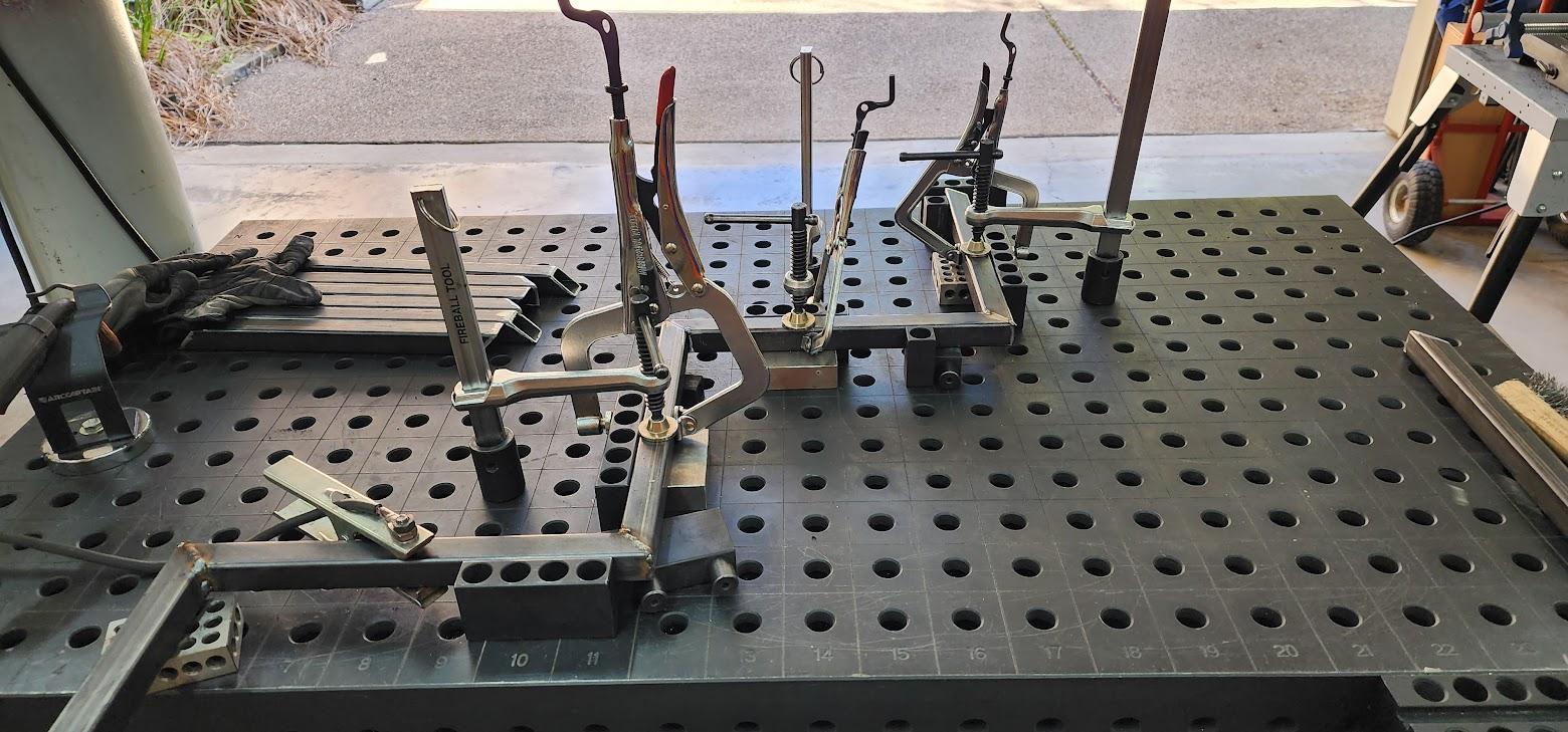
To ensure every frame stayed square, I used the fixtures on the welding table. Because of that setup, I could only weld one end of a frame at a time. Rather than completing one frame from start to finish, I worked in batches. First, I welded one end and one wheel plate assembly on all twelve frames. Then I went back through the entire stack to weld the opposite end.

Once a frame had both ends assembled, it was time to flip it...and flip it again...and then stand it on edge...and flip it once more so every joint could be fully welded for strength.

There was a lot of lifting today.

By the end of the day, though, all twelve base frames were complete.

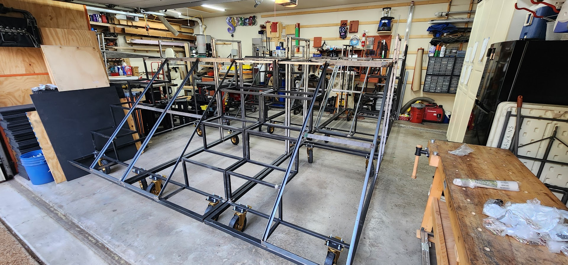
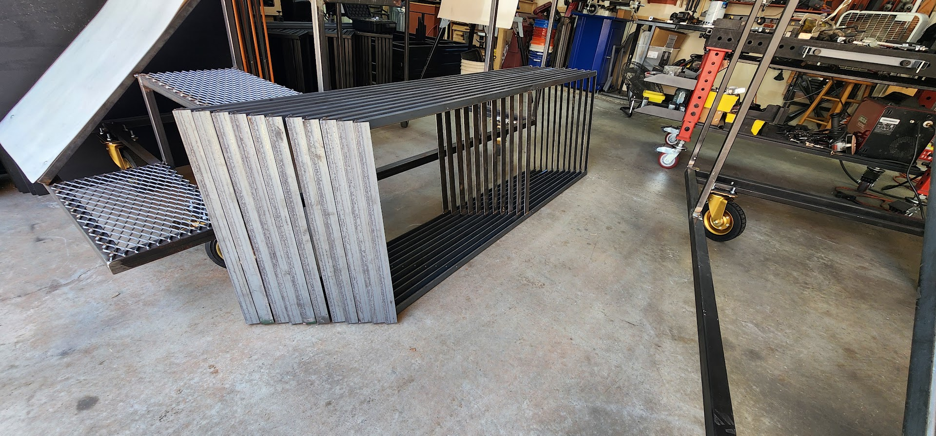
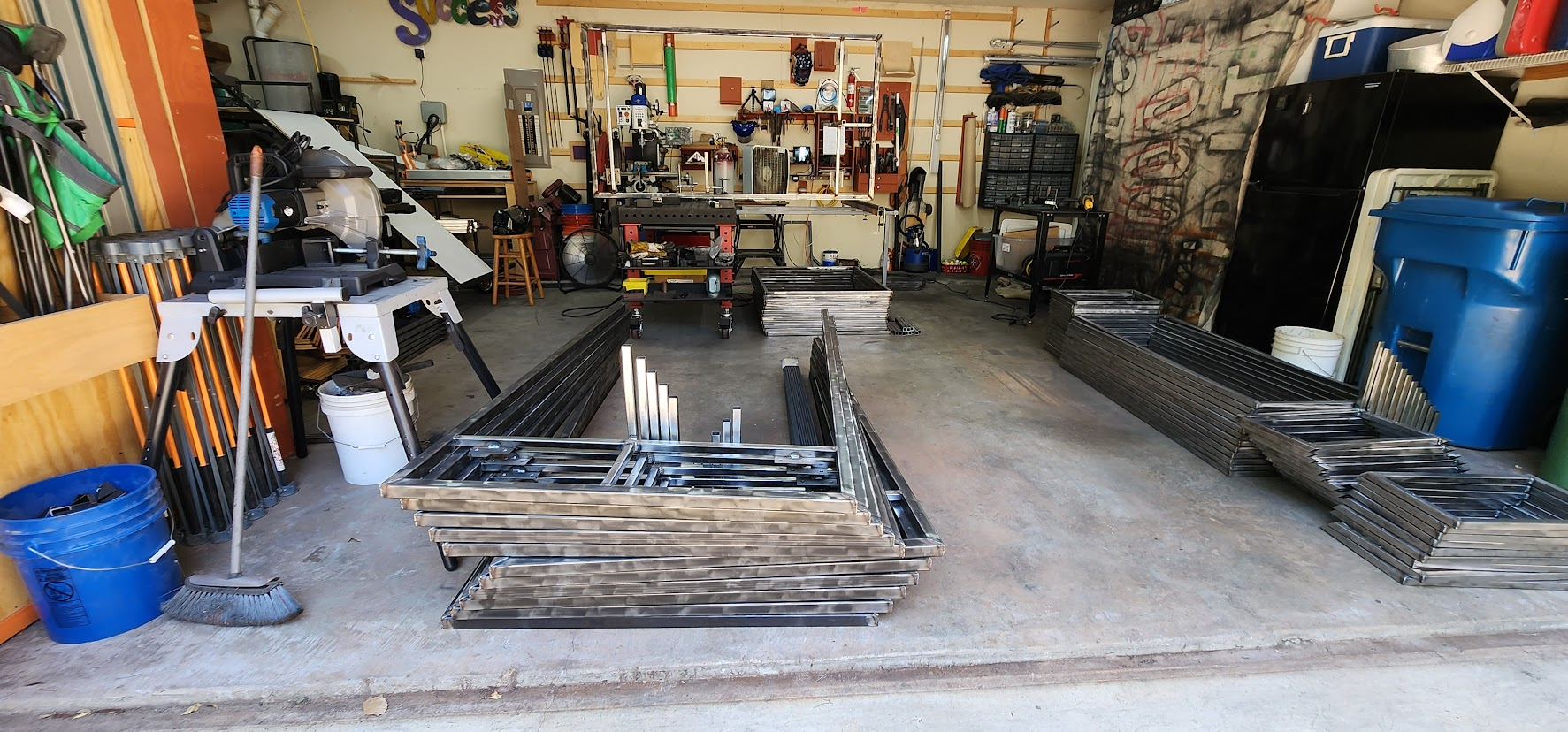
Standing back and looking around the shop, it was rewarding to see how far the project has come in just two weeks since the steel was delivered. The pile of raw stock that covered the shop floor is steadily disappearing, replaced by organized subassemblies. Even better, those subassemblies are now beginning to come together into larger assemblies that actually resemble parts of the finished props.

Today felt like one of those milestones that reminds you the finish line is getting closer. There's still plenty of welding ahead, but for the first time it feels like we're building props instead of just cutting steel.

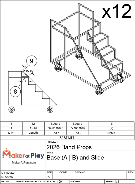
Engineering drawing: Base A dimensions and part list

Open on YouTube

Friday, June 26, 2026

June 26, 2026 – A Fixture for the First Step

Tonight was a shorter shop session, but it was another opportunity to check an important subassembly off the list.

The focus for the evening was building all twelve lower step assemblies. While they aren't the largest components of the prop, they presented an interesting fixturing challenge.

Most of the subassemblies I've built so far have been relatively flat. The pieces simply lay on the Fireball welding table while the fixtures hold everything square during welding.

The lower step assembly was different.

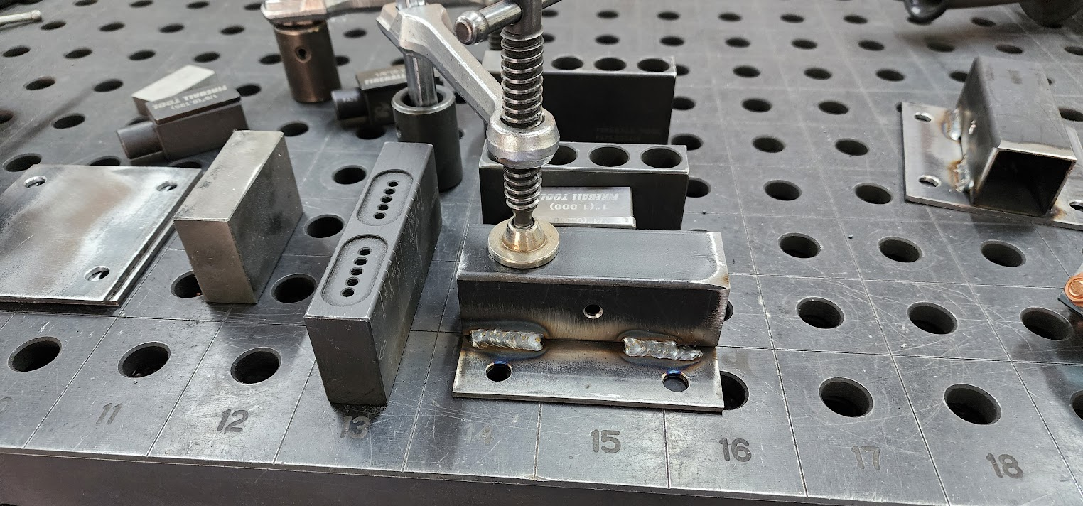
Each assembly includes an 11-inch vertical support welded at a 90-degree angle beneath the first step. To fixture that correctly, I needed to stand the step on its edge so the support could lay flat on the welding table.

That may sound like a small detail, but it made a big difference.

By having the support resting on the table, I could use my fixtures to control all three critical dimensions at once. The fixture kept the support perfectly square to the step in both the X and Y directions, while a stop block established the exact length of the support. Even if there were tiny variations in the cut lengths, every finished assembly would end up identical.

That's one of the things I enjoy most about production work. Sometimes the real challenge isn't the welding itself, it's figuring out how to build a fixture that makes every part come out the same.

Once the fixture was dialed in, the rest of the evening went quickly. One after another, all twelve lower step assemblies were welded together with confidence that each one matched the last.

Another stack of completed subassemblies.

Another step toward twelve finished props.

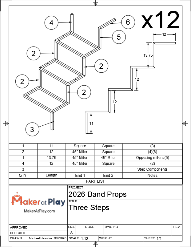
Engineering drawing: three steps subassembly dimensions and part list

Open on YouTube

Thursday, June 25, 2026

June 25, 2026 – More Progress and Material Planning

Tonight was a shorter session in the Maker At Play workshop, but every evening in the shop moves the project one step closer to the finish line.

The welding task for the night was straightforward. I combined two smaller components into a single subassembly that will eventually become part of the staircase assembly. It wasn't a particularly flashy milestone, but building props like this is all about completing dozens of these smaller assemblies before they come together into something much larger.

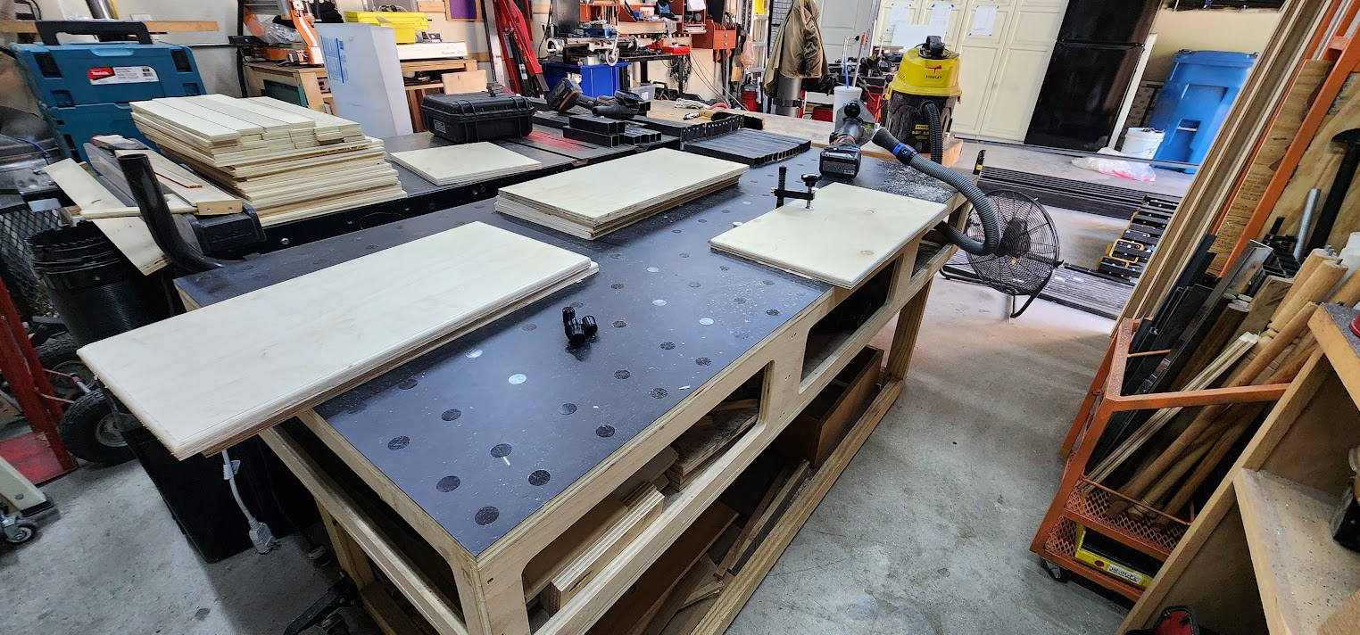
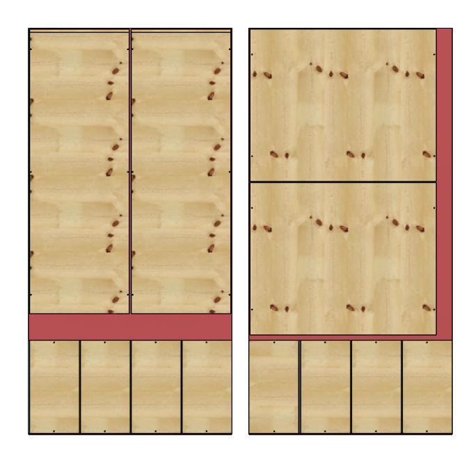
While the welder was cooling down, I also finalized another important piece of the project: figuring out exactly how much plywood we'd need for all twelve props.

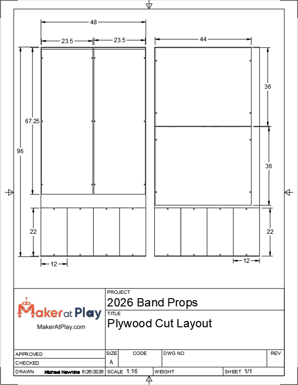
Each prop requires six plywood pieces:

  • Four stair treads measuring 22" × 12"
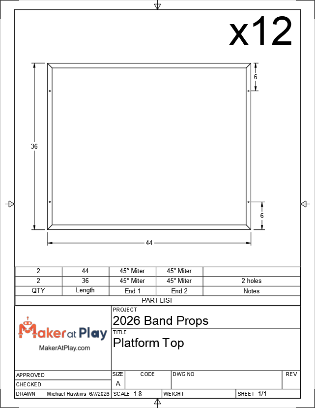
  • One top platform measuring 44" × 36"
  • One slide measuring 68" × 23.5"

After laying everything out, I found an efficient cutting plan. Two platform tops can be cut from one sheet of plywood, while two slides can be cut from a second sheet. The remaining material from those two sheets provides enough space to cut all eight stair treads needed for those same two props.

That means every pair of props can be built from just two sheets of plywood.

With twelve props to build, we'll need a total of 12 sheets of plywood.

One of the things I enjoy about projects like this is that they require both fabrication and planning. Every efficient cut saves material, reduces waste, and makes construction go a little smoother. Spending time optimizing the layout now means less money spent and fewer surprises once the full production run is underway.

Not the biggest milestone of the project, but another productive evening and another item checked off the list.

Engineering drawing: plywood cut layout with dimensions

Open on YouTube

Wednesday, June 24, 2026

June 24, 2026 – Wheel Plate Sub-Assemblies

Tonight's goal was to finish building the wheel plate subassemblies.

These assemblies are an important part of the prop because they tie together the wheel mounting structure with the first step of the staircase. By combining these into a single subassembly now, the final assembly of each prop will be much faster and more repeatable.

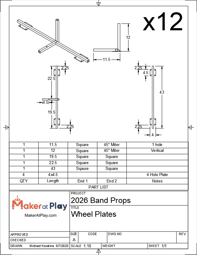
The first step was welding together the 11.5-inch and 12-inch pieces that form the side of the first step and the vertical support for the second step. Once all twelve of those assemblies were complete, I welded the 19.5-inch and 22.5-inch wheel plate bars to each side, completing the full wheel plate subassembly.

One detail that required extra attention is that these subassemblies are not all identical. Since the final props are built as mirrored pairs, six props have the staircase on the left side while the other six have it on the right. That meant the 19.5-inch and 22.5-inch wheel plate supports had to be swapped on half of the assemblies to create left-hand and right-hand versions. It was a small detail, but one that would become very important when these subassemblies were eventually welded to the base frames.

As the project progresses, the fixturing challenges continue to evolve.

Most of the early subassemblies were essentially flat, with every piece resting in the X-Y plane of the welding table. This assembly introduced another dimension. Part of the subassembly extends vertically above the table, so I needed a fixture that controlled not only its position on the table but also its height and angle.

This turned into another fun fixturing project using the Fireball Tool Tooth Block fixture, a 6-inch Extension Block, and a Stepped Fence Block to support the vertical member. Fence blocks at the three mounting points established positive reference surfaces that match where this subassembly will eventually attach to the base frame.

That was the real goal of the fixture.

Rather than simply holding the pieces while welding, it ensured every finished subassembly would be positioned identically. When it comes time to weld these onto the base frames, everything should line up exactly as intended without having to adjust or force parts into place.

The more I work through this production run, the more I appreciate the time spent designing good fixtures. The welding itself is often the easy part. The real challenge is creating a process that allows twelve identical assemblies to come off the table with the same dimensions every time.

Another twelve subassemblies completed.

One more step toward a full set of staircase props.

Engineering drawing: wheel plates sub-assembly dimensions

Open on YouTube

Tuesday, June 23, 2026

June 23, 2026 – Wheel Plates

Tonight was all about wheel plate production.

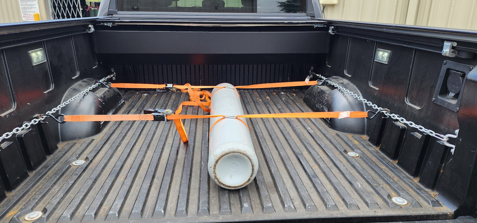
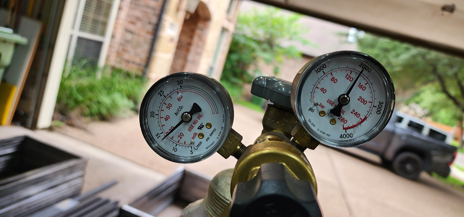
Before any welding could begin, there was one errand to take care of. During my lunch break at work, I made a quick trip to Airgas to swap out my shielding gas cylinder. Running out of gas in the middle of a production run is the last thing I wanted, so it was one less thing to worry about once I got home and headed into the shop.

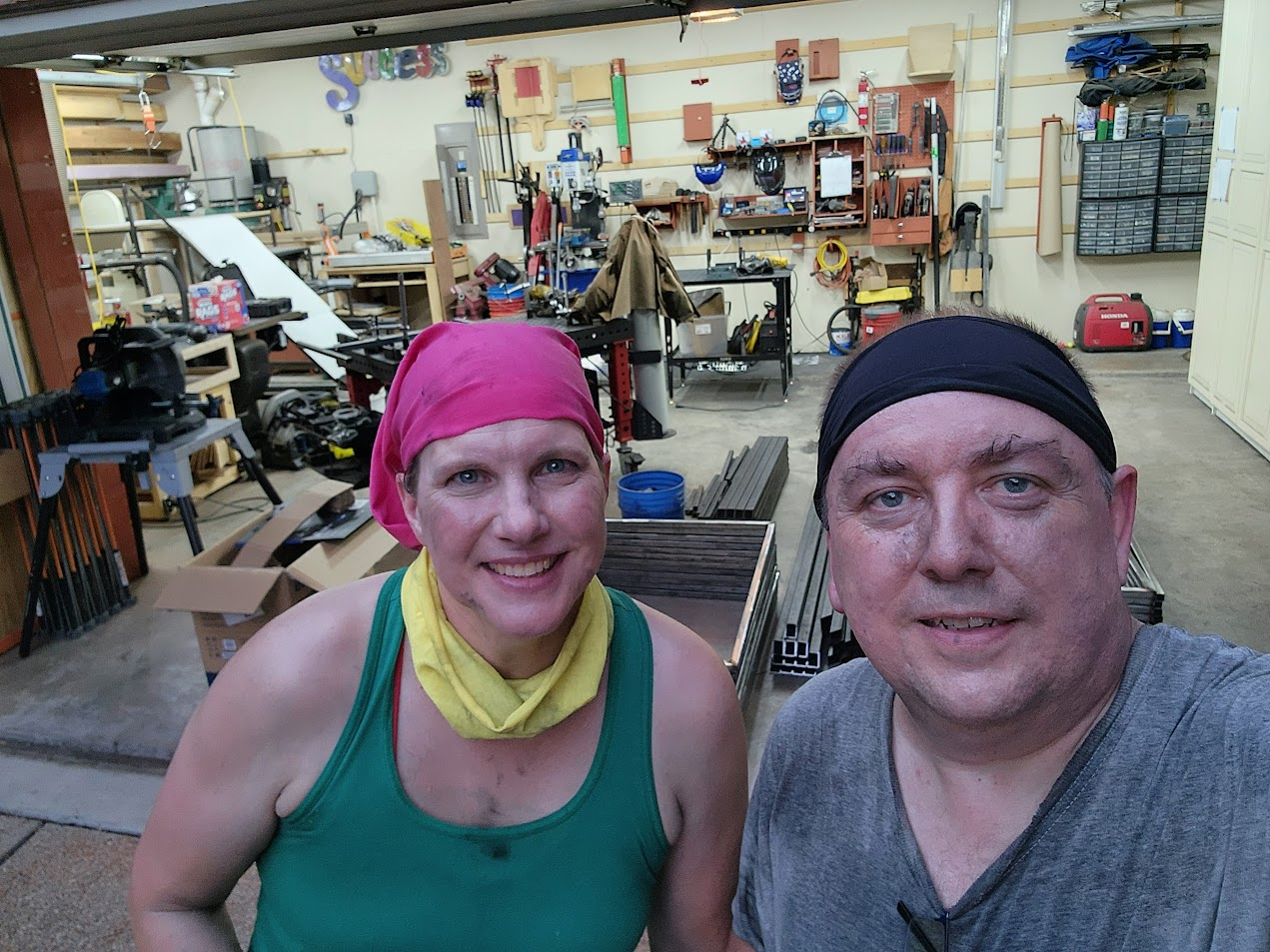
While I was at work, Susie spent part of the day cleaning up the wheel plate pieces that had been cut earlier. Having another set of hands taking care of prep work makes a huge difference when you're building twelve of everything.

I began the evening by sorting the large pile of 12-inch tubing pieces that had been cut several days earlier. Multiple subassemblies use these parts, so I wanted to separate them into the correct groups before welding. It was a simple organizational task, but one that helps avoid mistakes later when dozens of nearly identical parts are spread across the workshop.

With everything organized, it was time to weld.

The focus for the night was attaching all 48 wheel plates to their square tube supports. These were divided into three different assemblies:

  • The 43-inch wheel support, which receives two wheel plates
  • The 19.5-inch support, which receives one wheel plate
  • The 22.5-inch support, which also receives one wheel plate

Each assembly required its own dedicated fixture. Once the fixture was dialed in, I could repeatedly position each part in exactly the same location, making every assembly consistent while also speeding up production.

This is one of the benefits of spending time building fixtures. The first part always takes the longest. The next eleven come together much more quickly because the setup work has already been done.

By the end of the evening, all 48 wheel plates had been welded to their supports and were ready for the next phase of assembly.

Another stack of completed parts.

Another productive night in the Maker At Play workshop.

Engineering drawing: wheel plates sub-assembly dimensions

Open on YouTube

Monday, June 22, 2026

June 22, 2026 – Platform Legs

Another productive evening in the Maker At Play workshop.

While I was at work during the day, Susie tackled another batch of prep work by cleaning all of the platform legs and the long wheel plate bars. It's one of those jobs that isn't particularly glamorous, but it saves me valuable shop time in the evenings and keeps production moving.

Tonight's focus was welding the platform leg assemblies.

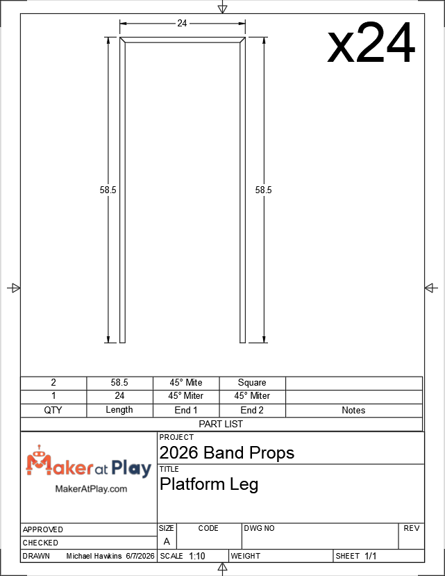
Each leg assembly consists of three pieces: a 24-inch cross member and two 58.5-inch vertical legs. Together, these assemblies will support the platform that sits at the top of each staircase.

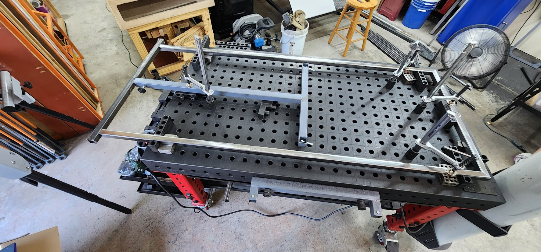
One challenge with these parts is their size. The 58.5-inch legs are longer than my Fireball welding table, so I had to get a little creative with the fixturing. I used a set of support legs beyond the end of the table to establish a consistent reference point for the bottoms of the vertical members. Combined with the fixtures on the table itself, this allowed every assembly to be held square and at the correct dimensions despite extending well past the edge of the table.

Once the fixture was dialed in, the rest became a matter of repetition. One assembly after another came together, and by the end of the evening all 24 platform leg assemblies were welded.

It's another one of those production nights where the progress doesn't immediately look dramatic, but every completed subassembly brings the project one step closer to final assembly.

The stack of finished parts continues to grow, and the pile of raw steel continues to shrink. That's exactly the kind of progress I like to see.

Engineering drawing: platform leg dimensions and part list

Open on YouTube

Saturday, June 20, 2026

June 20, 2026 – Steps and Platform Tops

Another full day dedicated to band props.

Production continued at a steady pace, with both Susie and me working on different parts of the build to keep the assembly line moving.

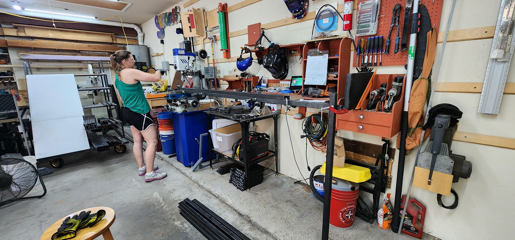
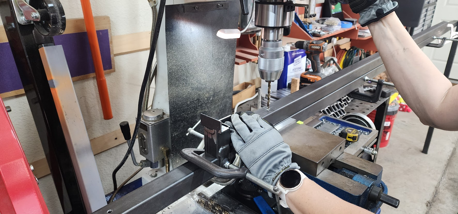
While I was in the workshop welding, Susie spent the day drilling mounting holes in the remaining 84-inch pieces and cleaning another batch of steel. Every hole drilled and every piece cleaned means less work later when the larger assemblies start coming together.

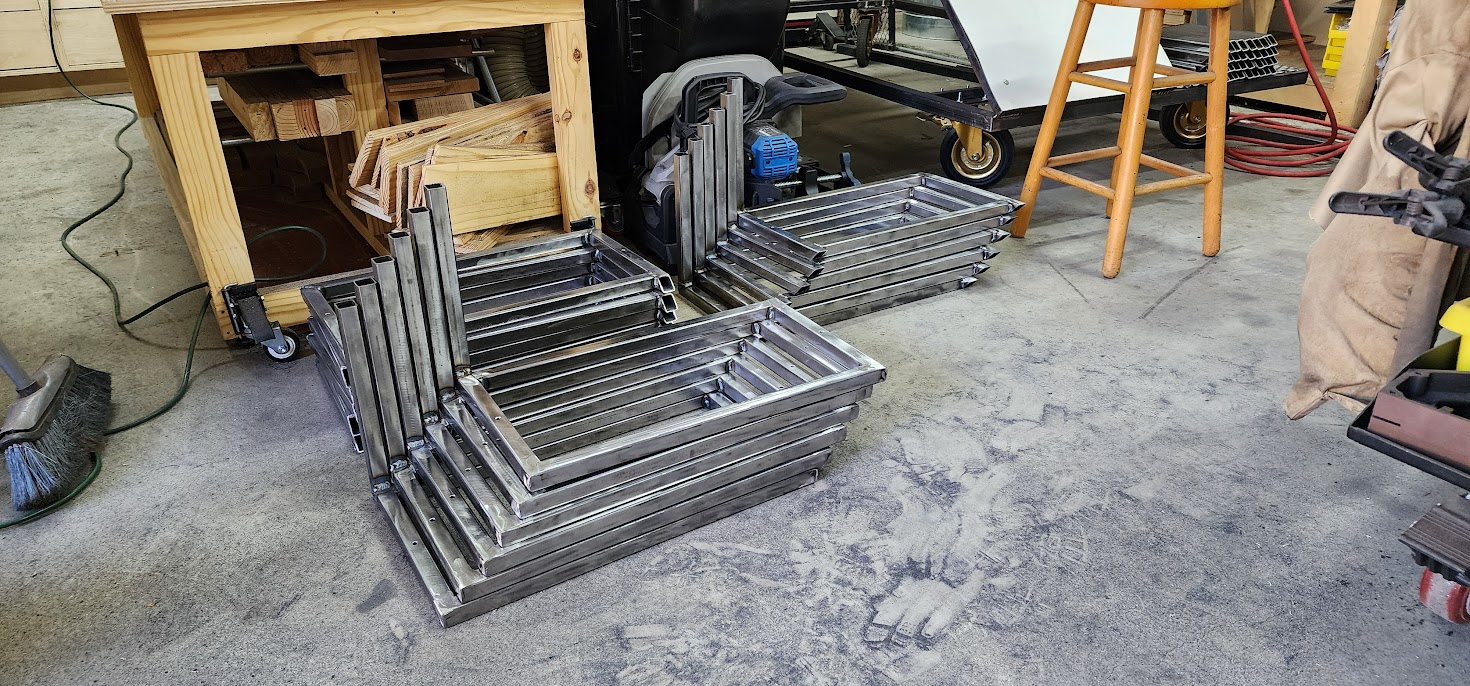
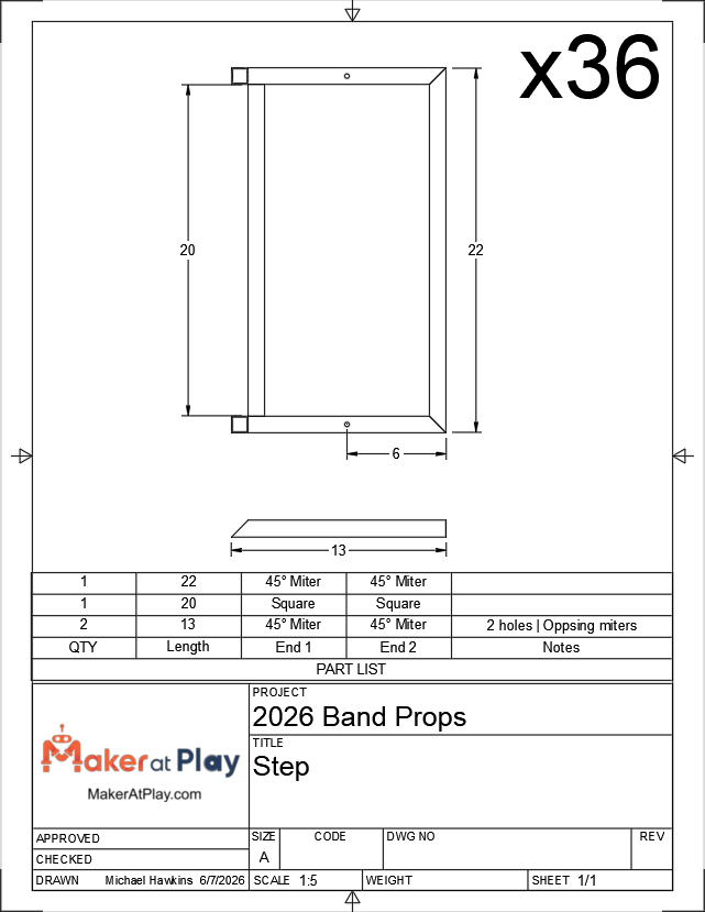
My focus for the day was finishing the stair subassemblies. I welded the remaining 18 steps, completing all 36 stair assemblies needed for the twelve props.

With the steps finished, I moved on to the platform tops, welding all twelve of those assemblies as well.

One thing I've learned building multiple props is that efficiency comes from batching similar work together. Instead of constantly changing tools, fixtures, and setups, I try to complete an entire type of assembly before moving on to the next. Once a fixture is dialed in and the welder settings are just right, it's much faster to build all twelve than it is to keep switching back and forth between different parts.

By the end of the day, two major groups of subassemblies were complete. The finished stacks of stair assemblies and platform tops were beginning to fill the workshop, replacing the piles of loose steel that had occupied the floor just a week earlier.

The transformation from raw material to finished parts was becoming more noticeable with every work session.

Engineering drawing: platform top dimensions and part list

Open on YouTube

Friday, June 19, 2026

June 19, 2026 – Welding Begins

Today marked a major turning point in the project.

For the past week, the workshop has been filled with measuring, cutting, organizing, and drilling parts. While all of that work was necessary, today was the day those individual pieces finally started becoming props.

The morning was spent finishing more of the production prep. While Susie continued drilling mounting holes, I cut the remaining 84-inch tubing and worked through the last of the stock material. Once the cutting was complete, I switched to the grinder to clean the steel pieces, removing mill scale and preparing the joints for welding. It also has the added benefit of giving the paint a much better surface to adhere to later.

At this point, every piece of steel had been cut to its final dimensions except for the slide supports. I'm intentionally leaving those until the end so I can take final measurements directly from the completed stair assemblies before cutting them.

With the fabrication prep nearly complete, it was finally time to fire up the welder.

I started with the stair subassemblies, welding together the first 18 of the 36 stair steps that will be needed for all twelve props. Each prop has three welded stair assemblies, so by the end of the day I was halfway through one of the most repetitive welding tasks of the project.

There's something satisfying about reaching this stage. After days of cutting steel into hundreds of individual pieces, those parts finally begin disappearing into completed assemblies. The workshop starts looking less like a metal supply warehouse and more like a fabrication shop.

Production has officially shifted from preparing parts to building props.

There's still a long road ahead, but today felt like the beginning of the assembly line.

Engineering drawing: step subassembly dimensions and part list

Open on YouTube

Wednesday, June 17, 2026

June 17, 2026 – Production Cutting Marathon

Another Wednesday night in the Maker At Play workshop.

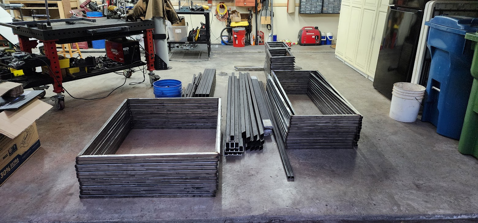
The metal arrived last Friday, and tonight marked my fifth straight day of cutting material. At this stage of the project, it isn't the glamorous part of prop building. There aren't many visible results yet. Instead, it's about transforming long sticks of steel into a mountain of accurately sized parts that will eventually become twelve staircase props.

Tonight's cutting list included:

  • 12 pieces of 24-inch angle iron for the slide supports, cut from four 73-inch stock pieces
  • 12 pieces of 22-inch 1.5-inch flat bar, cut from three 89-inch stock pieces
  • 12 pieces of 24-inch 1.5-inch flat bar, cut from three 97-inch stock pieces
  • 40 wheel mounting plates measuring 4.5 inches each, cut from ten 47-inch lengths of 4-inch flat bar stock

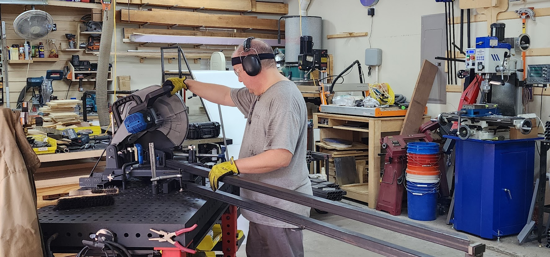
Once those were complete, I moved on to a larger batch operation. Since the saw was already configured for 90-degree cuts, I cut 48 pieces to 24.5 inches long. Then I reconfigured the saw for 45-degree cuts and split those pieces in half, producing 96 parts that measured approximately 12 inches long with one square end and one mitered end.

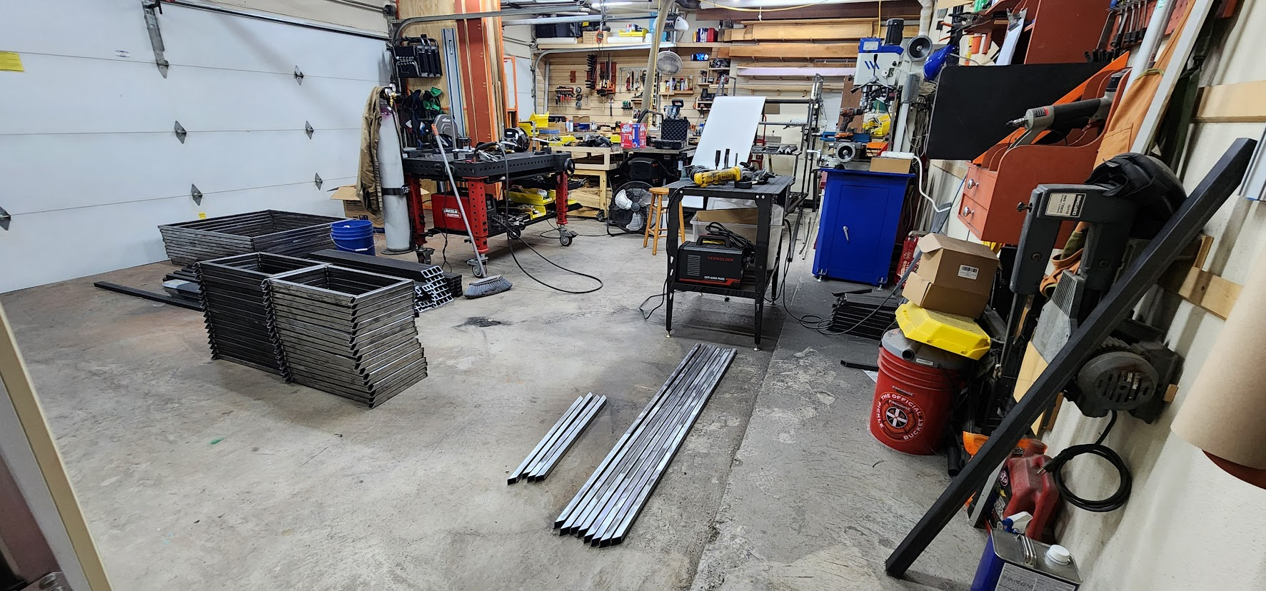
When all was said and done, 172 pieces were cut during the evening.

Organized stacks of cut steel stock on workshop floor

One of the realities of building multiple props is that fabrication becomes a manufacturing exercise. The challenge shifts from figuring out how to build one prop to figuring out how to efficiently build twelve identical props. That means spending nights like this one standing at the saw, working through stock material, organizing parts, and preparing for the welding phase that comes next.

It's not the most exciting stage of the project, but every finished part is one less cut that has to be made later.

The growing stacks of labeled steel may not look like much yet, but they represent steady progress. Every piece cut tonight is one step closer to transforming a pile of raw metal into a field full of staircase props.

Open on YouTube

Tuesday, June 16, 2026

June 16, 2026 – Day 4 of Production

Day 4 of turning a pile of stock metal into the 600 individual pieces needed to build 12 rolling stair props.

At this stage, the workshop doesn't look much different than it did when the steel was delivered. Instead of finished props, there are stacks of cut tubing, flat bar, and angle iron slowly replacing stacks of full-length stock.

It's not the most exciting part of the project, but it's one of the most important.

Every piece has to be measured, cut, and organized before the first production weld can happen. A mistake now doesn't just affect one prop—it gets repeated twelve times.

The prototype taught me what needed to be built. Now it's time to manufacture the parts that will become the full set.

This phase reminds me a lot of manufacturing. The focus shifts from creativity to consistency. Every cut needs to be accurate. Every matching part needs to be identical. The goal isn't just to build one good prop; it's to build twelve props that all fit together exactly the same.

It's repetitive work, but I actually enjoy it. There's something satisfying about watching a pile of raw material slowly transform into organized stacks of parts, knowing that each one brings the project another step closer to taking the field.

Still a long way to go, but progress is being made one cut at a time.

Open on YouTube

Monday, June 15, 2026

June 15, 2026 – Cutting and Drilling

Continued cutting metal stock into final pieces and drilling holes.

Sunday, June 14, 2026

June 14, 2026 – Cutting and Drilling

Continued cutting metal stock into final pieces and drilling holes.

Saturday, June 13, 2026

June 13, 2026 – Cutting and Drilling

With the metal unloaded into the workshop, it was time to start turning full-length stock into actual prop components.

Today marked the beginning of what will probably be the longest phase of the project: cutting hundreds of pieces to their final dimensions and drilling the holes needed for assembly.

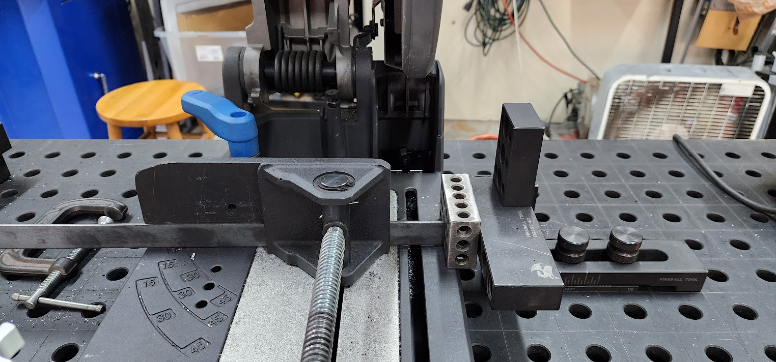
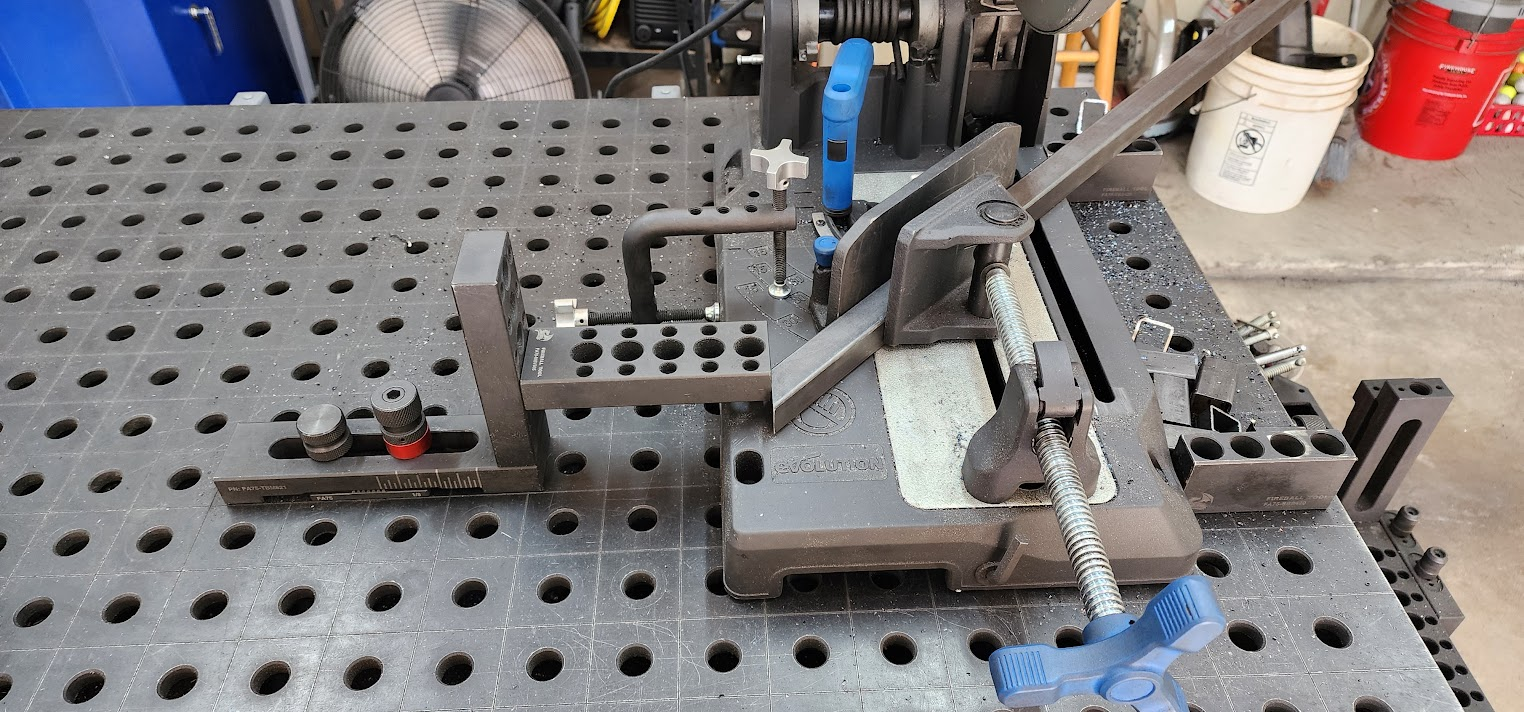
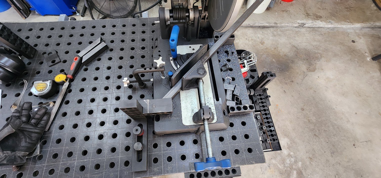
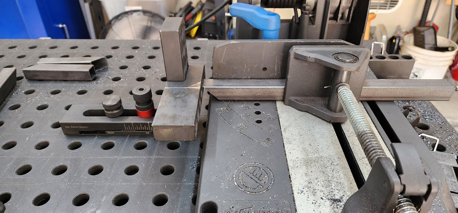
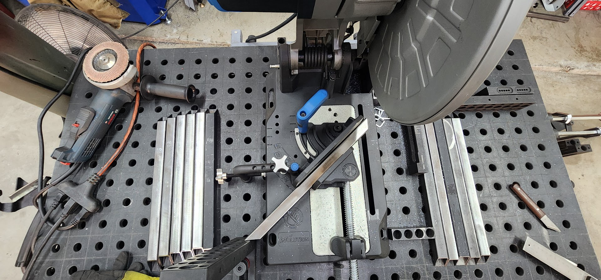
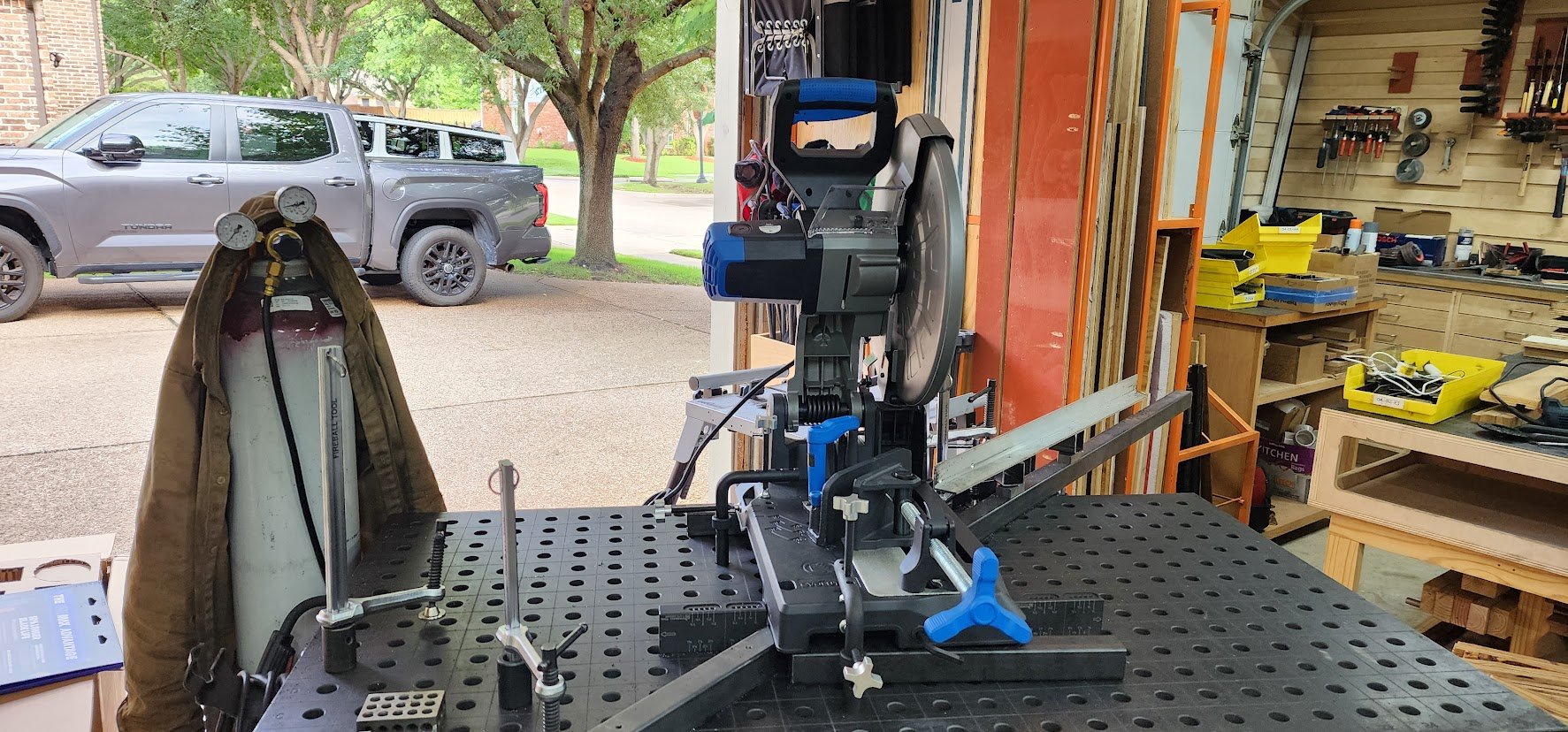
I started by setting up my chop saw with a fence for making repeatable 45-degree miter cuts. I knew there were hundreds of pieces ahead of me, so taking the time to properly set up the saw would pay dividends over the next several days. When you're making the same cut dozens of times, repeatability becomes just as important as accuracy.

Once the saw was dialed in, I started working my way through the cut lists one stock length at a time.

When building a single prototype, you can often cut a part when you need it. Building twelve identical props is a completely different process. Before any serious welding can begin, every matching part needs to be cut, drilled, and organized.

It's a bit like preparing ingredients before cooking a big meal. The more prep work that's done up front, the smoother the assembly process becomes later.

The goal over the next several days is to work through the pile of steel one stock length at a time, transforming it into hundreds of accurately sized parts. It's repetitive work, but it's also where consistency is established. If every part matches, the final assembly becomes much easier.

There's not a lot of glamour in standing at a saw or drill press for hours, but every finished piece is another step toward seeing twelve staircase props take shape.

The manufacturing phase has officially begun.

Open on YouTube

Friday, June 12, 2026

June 12, 2026 – Metal Has Arrived

The metal has arrived.

Now comes the easy part: turning a $3,300 pile of steel into 12 rolling stair props.

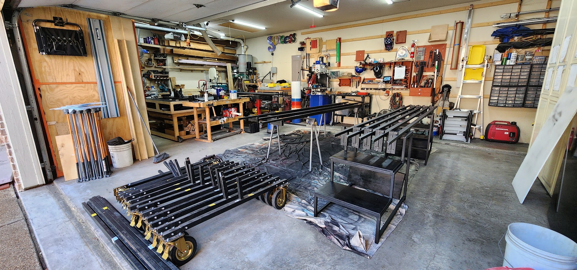
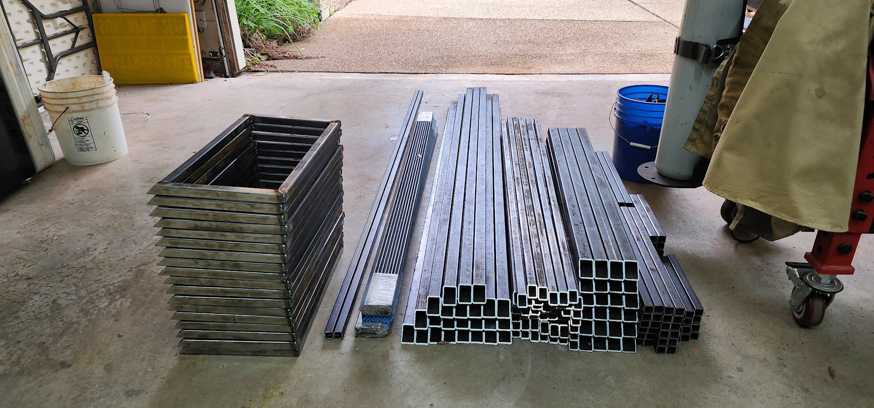
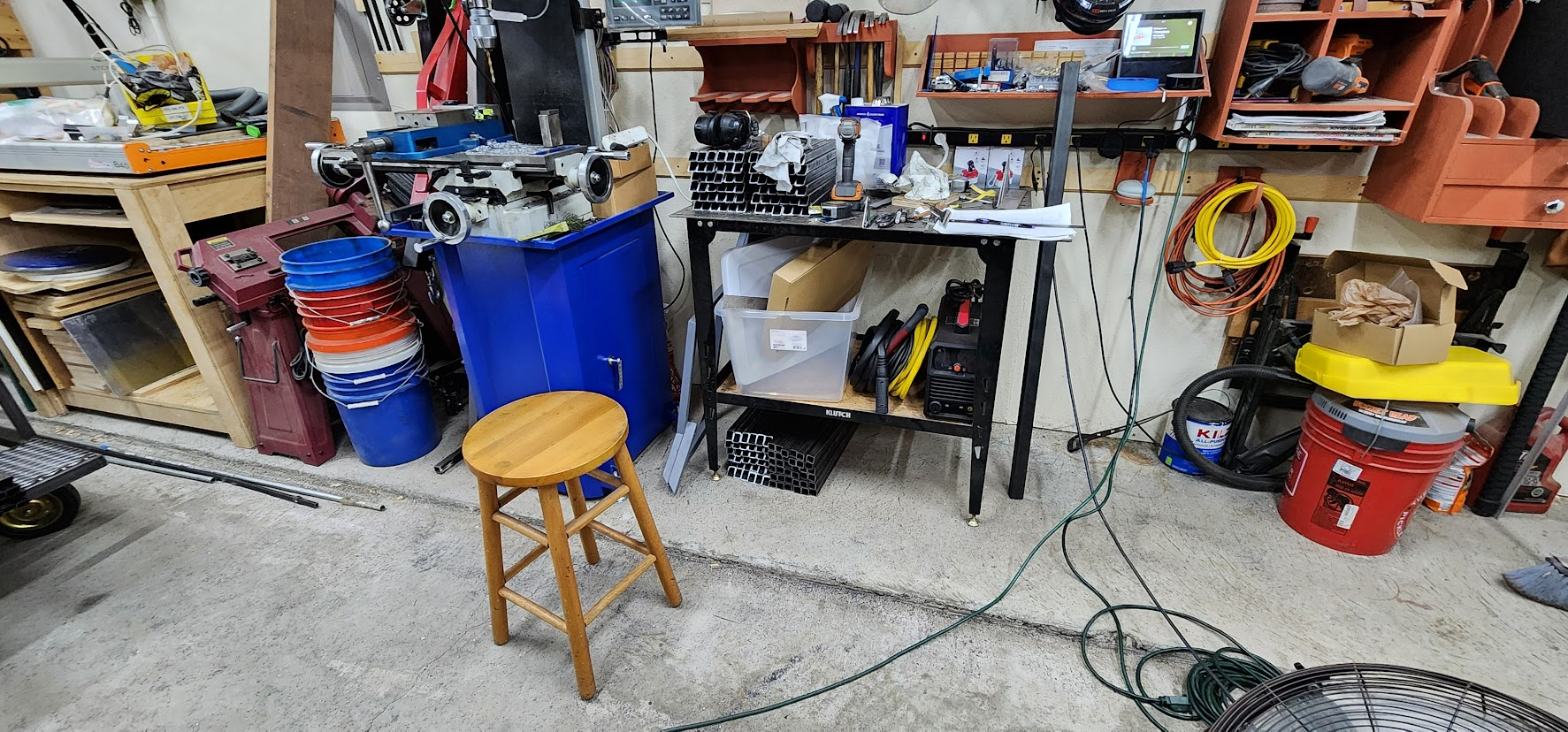
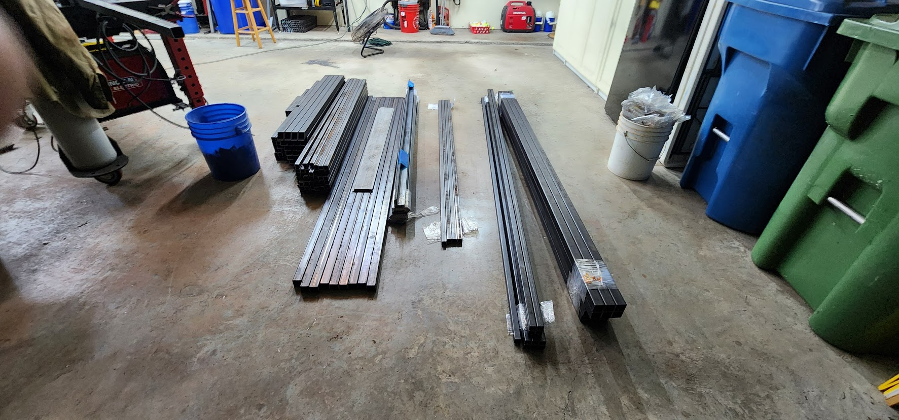
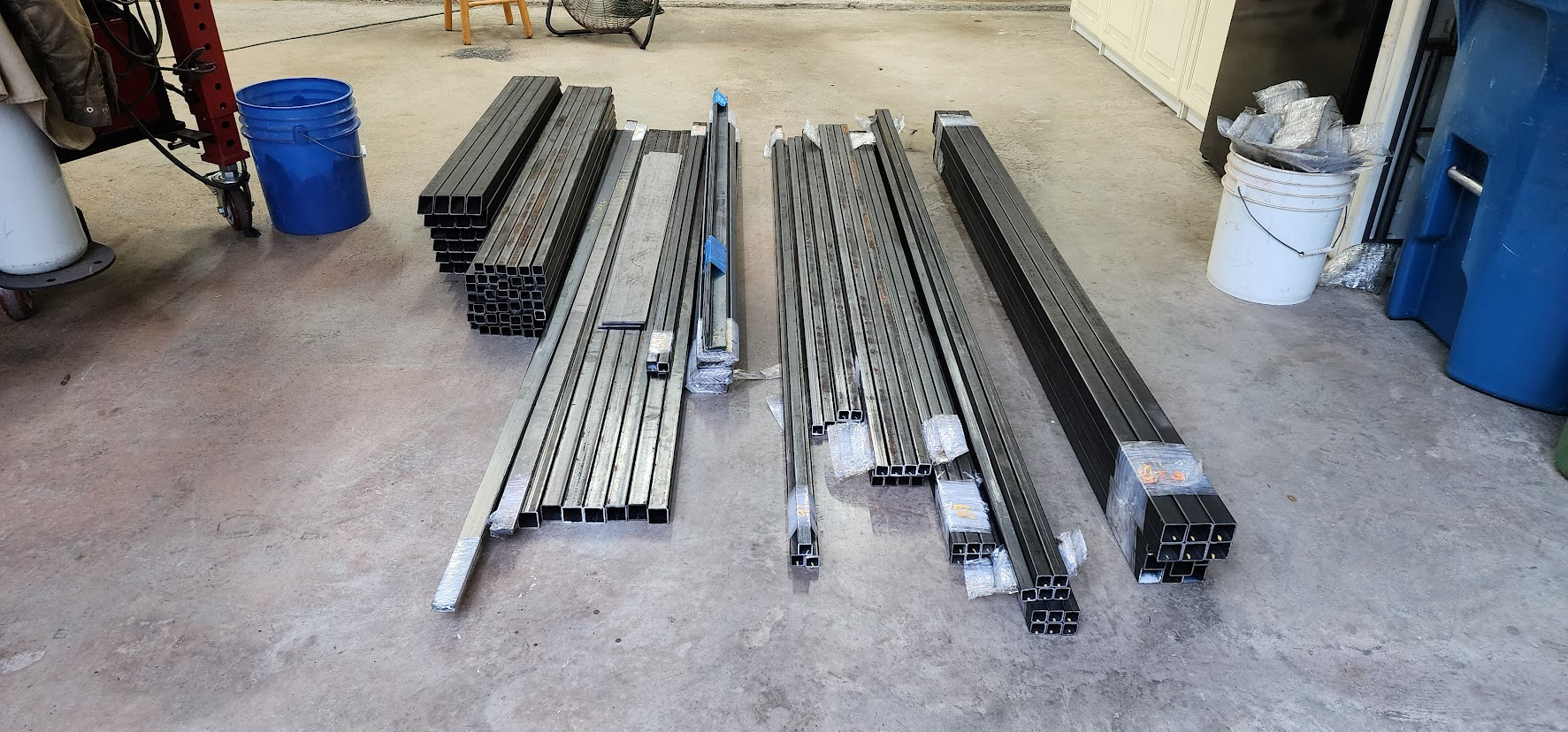
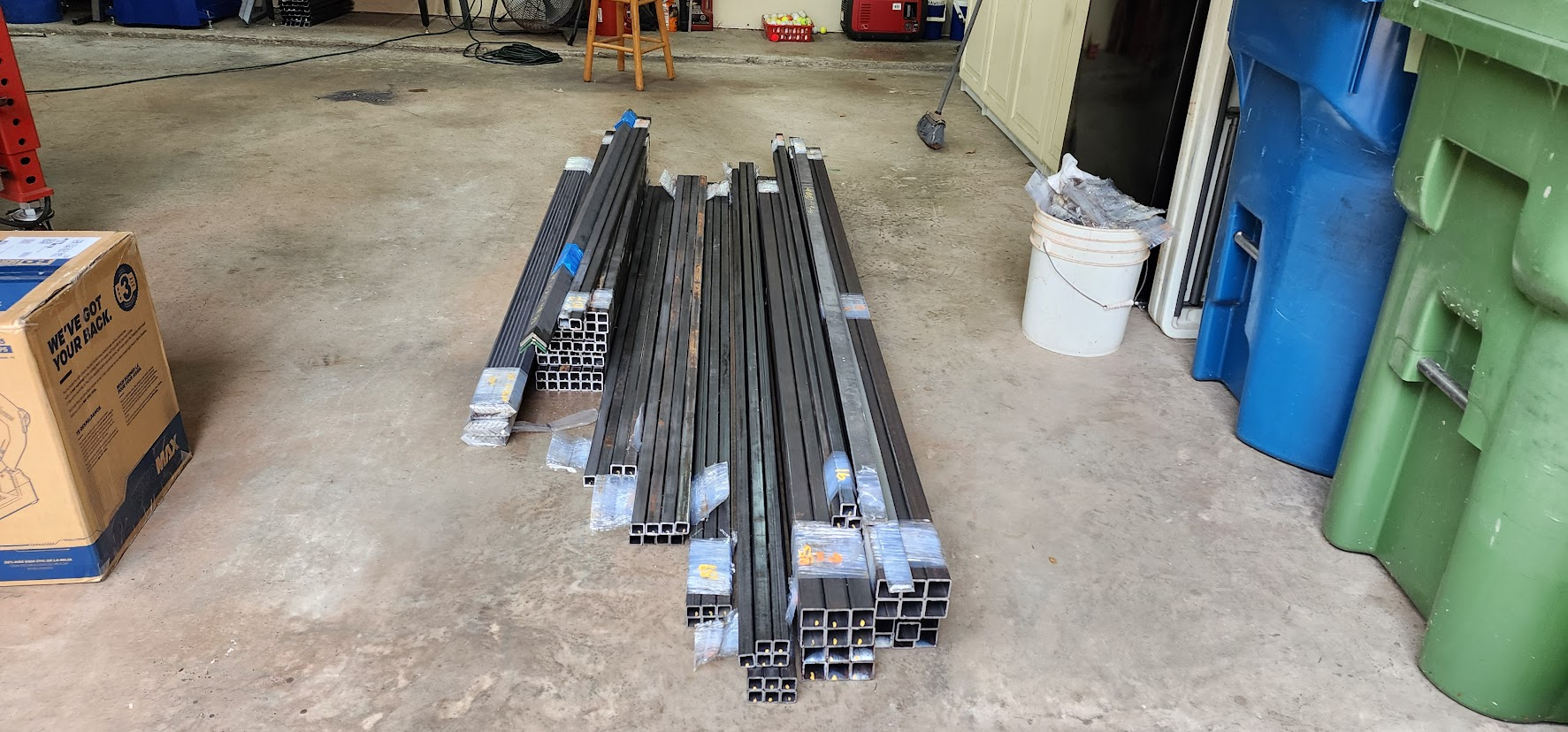
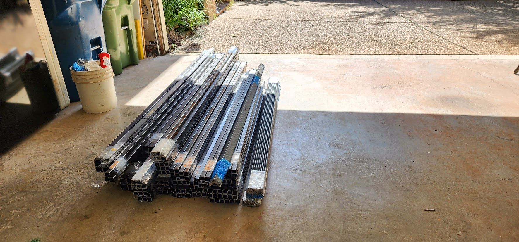
I've been purchasing metal from Metal Supermarkets in Lewisville since building my first metal props back in 2021. They delivered this year's order, consisting of 215 pieces of steel tubing, flat bar, and angle iron. Well, almost all of it. A few pieces weren't in stock and would be delivered the following Monday.

I'm certainly glad I opted for delivery. Looking at the stack of material that showed up, I'm not convinced my truck could have safely hauled all of it in a single trip.

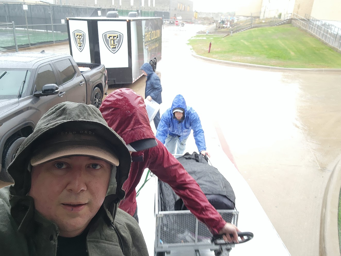
Even with the material delivered to the house, getting it into the workshop was no small task. It took John, Susie, the delivery driver, and me about twenty minutes to unload everything.

Once the truck pulled away, I stood back and looked at what had arrived.

More than 200 pieces of steel.

Over $3,300 worth of material.

And not a single prop in sight.

At this stage, all I could see was raw material. But hidden inside that pile were twelve staircase props waiting to be built.

The next challenge would be transforming those 215 pieces into more than 600 individual parts through a seemingly endless process of measuring, cutting, drilling, and welding.

One of the interesting things about projects like this is how different the beginning and the end look. Right now, it's just a pile of steel sitting on the shop floor. A few months from now, that same steel will be rolling across a football field as part of a marching band show.

But first, there are hundreds of cuts to make.

Time to get to work.

Open on YouTube

Thursday, June 11, 2026

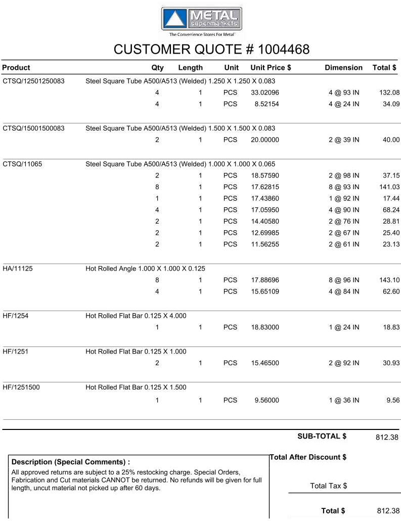
June 11, 2026 – Metal Order Placed

Placed metal order for the 12 stair props.

Metal Supermarkets customer order for stair prop materials

Wednesday, June 10, 2026

June 10, 2026 – Design Updates and Decision

Discussed changing the dock stages. The band director was thinking we might be okay with half the size of what they are currently — so just one 4 × 8 section for each dock.

We are also going to 10 front screens.

CAD mockup: revised dock stage with single 4 by 8 section

Saturday, June 6, 2026

June 6, 2026

Now that we have finalized the prop designs, I have completed the CAD drawings and begun planning for the build phase. Using those drawings, I have also mapped out the coroplast sheet layouts to optimize material usage and minimize costs.

Stair/Slide Props

The stair/slide props consist of six mirrored pairs (12 total). For each pair, we can produce all six side panels from three 5' × 10' sheets of 4 mm coroplast.

The artwork layout must follow the attached pattern so we can obtain the required panels while still printing on only one side of the coroplast. I have labeled each piece and take note on text orientation, as some pieces must be rotated to maximize material efficiency and ensure the artwork appears correctly once installed.

We will order these sheets uncut and perform the cutting ourselves. It would be helpful to include bleed along all cut lines to provide tolerance during cutting and to account for minor dimensional variations during assembly. I have also included measurements for all cut pieces.

One question: How many stair props need to accommodate a trombone? I plan to include flag troughs in all 12 props, but I assume not all of them require trombone holders.

Stages

I assume we want to cover three sides of each stage with coroplast. Based on that assumption, I have mocked up the stages using 4' × 8' sheets of 4 mm coroplast. The two stages would require a total of six sheets.

I have also included a design for a set of three-step stairs to provide access to the stages. These steps are 30 inches wide, with each step 12 inches tall. The final step onto the stage is 10.5 inches. The stair unit would sit on the ground during use and could be lifted and placed on the stage for transport on and off the field.

CAD mockup: stage with coroplast on three sides and three-step access stairs

Back Media Frames

For the back media frames, I would like to limit the design to no more than three sheets of 4' × 8' 10 mm coroplast per frame. This results in a total requirement of 21 sheets. I have included a mockup showing how three sheets will fit on each media frame.

CAD mockup: back media frame with three vertical coroplast panels

Current Field Layout

With the prop designs locked in, the current field setup is:

  • 12 stair/slide props — six mirrored pairs staged throughout the center of the show
  • 7 media frames
  • 2 stages
  • 6 front screens — exactly how many front screens would we like to have?
CAD field layout: stair props, media frames, stages, and front screens

Coroplast Order Summary

  • 18 sheets — 5' × 10', 4 mm (stair/slide props)
  • 6 sheets — 4' × 8', 4 mm (stages)
  • 21 sheets — 4' × 8', 10 mm (media frames)
  • 6+ sheets — 4' × 8', 4 mm (front screens; final count TBD)

Please review the attached layouts and let me know if you see any issues before we move forward with artwork and material ordering. I plan to order the metal and start building these in a week.

And, for reference, here is how I am planning to load the 12 stair/slide props into the two 26-foot box trucks. The four stages and media frames will fit on our 20-foot trailer. I am still working on where we can fit a single cart of front screens.

Tuesday, May 26, 2026

May 26, 2026 – From Prototype to Production

With the prototype updated based on our first round of feedback, it was time to take it back for another evaluation.

I loaded the revised prototype into my truck and headed to the band's audition camp. This year's camp was being held at Griffin Middle School while renovations were underway at The Colony High School. It gave the band director an opportunity to see the updated prototype in person and evaluate whether the design changes addressed the concerns from our first test.

The changes we made after the first round of feedback immediately paid off.

Lowering the platform and increasing its size made a noticeable difference. While the prop itself wasn't dramatically different, it felt much more stable. Lowering the platform by about a foot reduced the center of gravity, making the entire structure feel more secure. At the same time, the sides of the prop still extended roughly ten inches above the platform, giving performers the feeling that they weren't standing right on the edge. Sometimes the perception of safety is just as important as the actual engineering.

Another major improvement was replacing the expanded metal platform with plywood. The plywood flexed much less underfoot, creating a more solid and confidence-inspiring surface.

Based on that success, we also decided to replace the expanded metal stair treads with plywood. Besides providing a more stable walking surface, plywood greatly reduces the chance of costumes snagging if performers sit on the steps during the show.

As an added bonus, switching to plywood simplified the build. Cutting and fitting plywood is significantly faster than cutting expanded metal and then grinding every edge smooth.

By the end of the review, we had what every prototype hopes to achieve: confidence that the design was ready.

The prototype had answered the questions it was built to answer, and we received the go-ahead to move forward with production.

With the design now finalized, my attention shifted back to Fusion 360. The next step was updating the model one final time, designing each of the subassemblies, and producing the drawings that would guide the construction of all twelve props.

The prototype had done its job.

Now it was time to build the real thing.

Monday, May 25, 2026

May 25, 2026

I completed the latest changes to the prop, and I do think these updates make a big difference in the stability and overall feeling of standing on the platform and getting onto the slide.

I can bring it to Griffin anytime tomorrow. Just let me know what works best with the schedule.

Here is a video and some photos of the changes.

Open on YouTube

Sunday, May 24, 2026

May 24, 2026 – Prototype Slide Changes

Continued to work on changes to prototype slide.

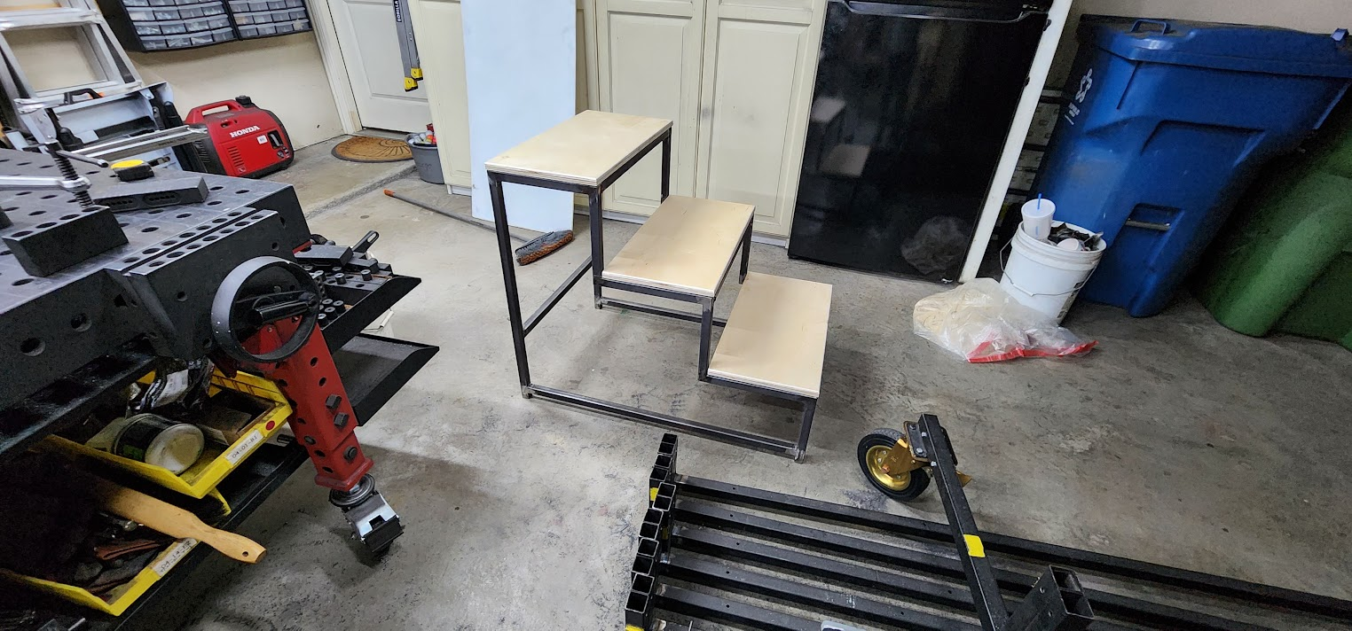
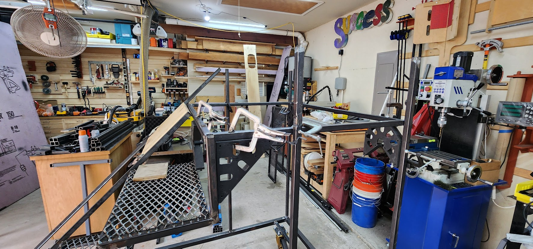
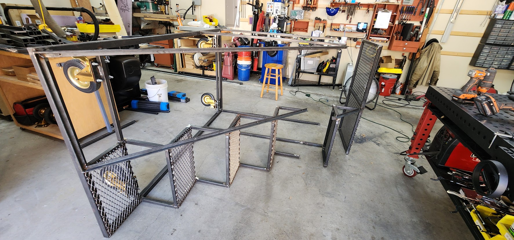
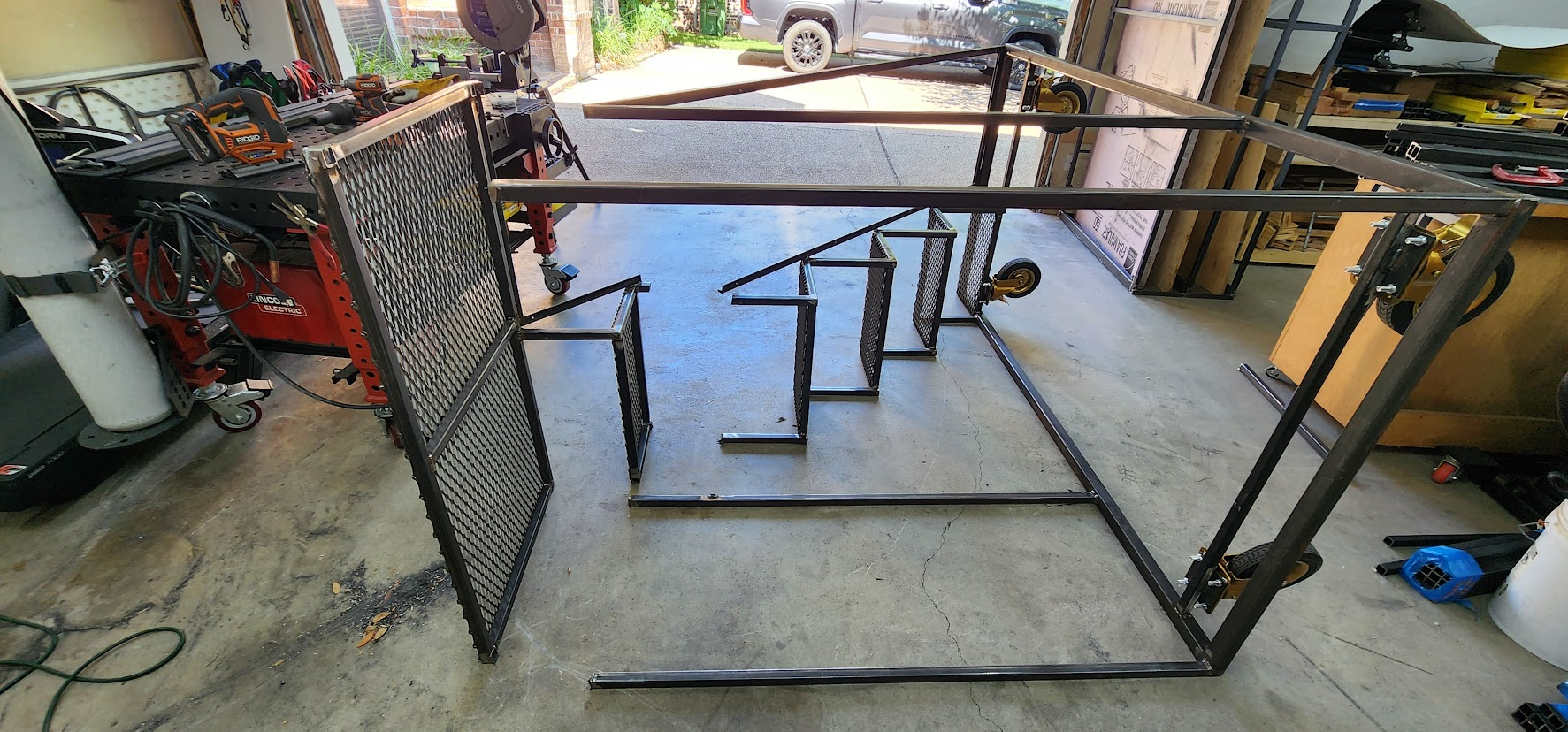
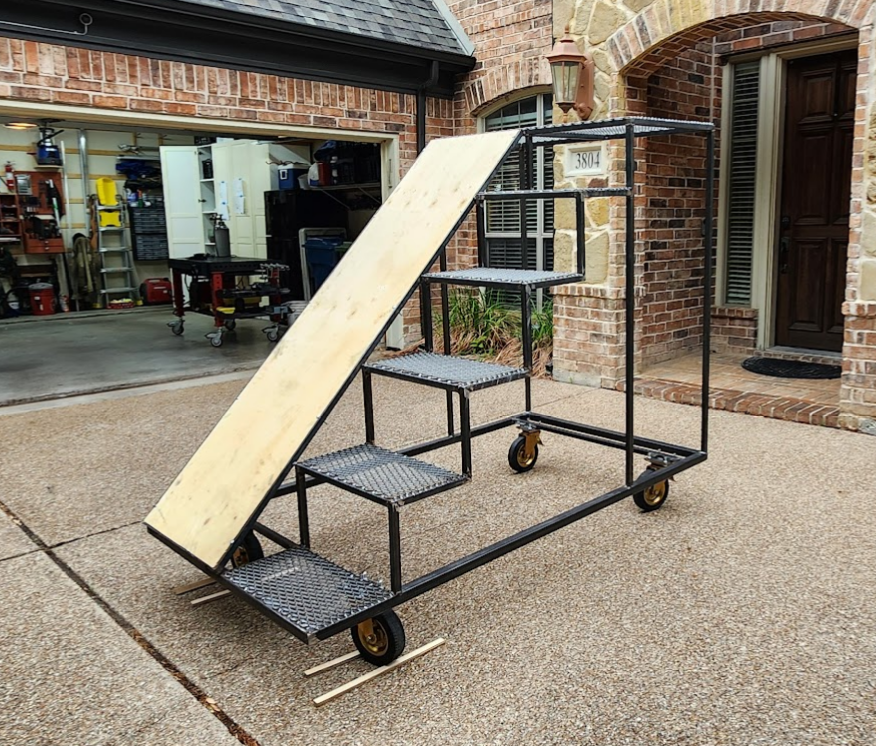
Prototype with plywood platform and stairs on casters in workshop

Saturday, May 23, 2026

May 23, 2026 – New Platform Welded

Welded together new platform for the prototype to apply feedback.

Friday, May 22, 2026

May 22, 2026 – Platform Redo

The feedback from our first round of testing was clear. The platform needed to be lower and larger.

Now came the part every fabricator dreads: cutting apart something you just finished building.

The first challenge was figuring out where to make the cuts. I wanted to preserve as much of the prototype as possible while removing only the pieces that needed to change. Every cut made now would save time rebuilding later.

Armed with a metal-cutting blade in my jigsaw and a cutoff wheel on the angle grinder, I started carefully removing the original platform.

I'll admit, I wasn't looking forward to this part of the project. I expected it to take most of the day just to free the platform from the rest of the structure.

Fortunately, it went much smoother than I expected.

It was still a fair amount of work, but once the first few cuts were made, the process became much more manageable. Before long, the original platform had been removed and the prototype was ready for its next evolution.

That was my goal for today's shop session.

I was also juggling a few personal shop projects, so rather than rushing into rebuilding the new platform, I focused on getting the old one removed cleanly and leaving the prototype ready for the next work session.

Sometimes progress doesn't mean adding new parts.

Sometimes the biggest step forward is having the confidence to cut apart something you already built because you know the next version will be better.

Open on YouTube

Sunday, May 17, 2026

May 17, 2026

Here is a mockup of the changes we discussed Thursday morning. After drawing this out, though, I do not think it would work as expected, so I drew another version that combines more of the feedback.

The thought is that increasing the size of the top platform and lowering it by one step would make it more stable and easier for the students to stand on and transition onto the slide.

This newer version below has the top platform at 4 × 3 ft without increasing the overall length of the prop, so it will still fit in the box trucks. It still has the sides extending upward to act as handles, and keeps the same side profile for coroplast. The angle of the slide is the same. I have also modeled a flag trough in the bottom.

Unless there are any objections to this design, I will modify the current prop's top platform to match it and bring the prop to Audition Camp on Tuesday, 5/26, so the students can test it again. Hopefully, that will finalize the design so I can start building in June.

Here are some mockups with coroplast to give an idea of what the sides might look like. Once we settle on the final prop design, I will provide measurements and guidance for the coroplast layout.

Thursday, May 14, 2026

May 14, 2026 – Putting Prototype to the Feedback Test

Today was an important milestone for the prototype. It was time to stop evaluating it in the workshop and see how it performed with the people who would actually be using it.

We loaded the prototype into my truck and took it to the high school for the band director to evaluate. During first period, he brought his class outside and invited students to climb the stairs and slide down so we could observe how the prop performed in a real-world setting.

This was exactly why I wanted to build a prototype before committing to twelve copies.

Almost immediately, one thing became obvious. While the students had no problem climbing the stairs or sliding down, many of them were noticeably uneasy standing on the top platform before making the transition to the slide.

Interestingly, the concern wasn't with the slide itself. Although it looks fairly steep, the students were comfortable once they committed to the slide. The slide angle worked just as we had hoped, which meant there was no need to redesign that portion of the prop.

The platform, however, was telling us a different story.

Our first thought was simply to make the platform larger, but increasing the overall footprint of the prop wasn't really an option. The dimensions had already been carefully planned so twelve props could fit into the school's two box trucks for transportation. Making every prop wider or deeper would create an entirely new logistics problem.

Instead, we decided the next prototype revision would focus on lowering the platform while increasing the amount of standing room available. The hope was that a lower center of gravity and additional space would make students feel more comfortable and confident when they reached the top.

This test reinforced exactly why prototypes are so valuable. CAD models can tell you whether something fits together. Structural calculations can tell you whether something is strong enough. But neither can tell you how a student will feel standing six feet in the air preparing to slide down.

Now that we had real feedback instead of assumptions, it was time to head back to the Maker At Play workshop and see if those platform changes would solve the problem before production began.

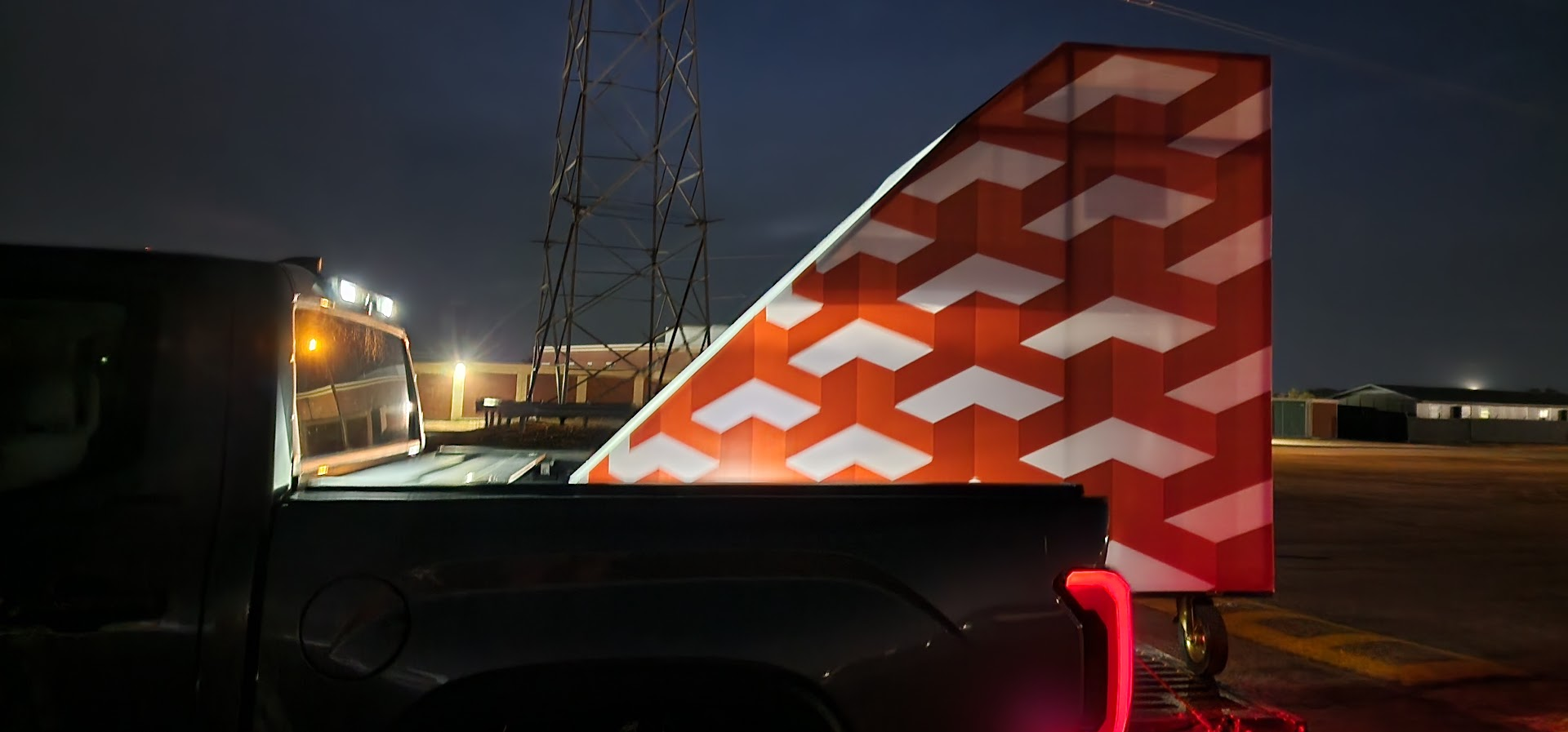
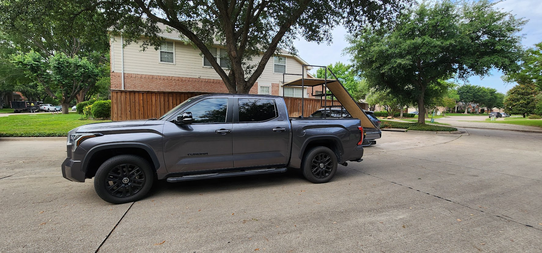
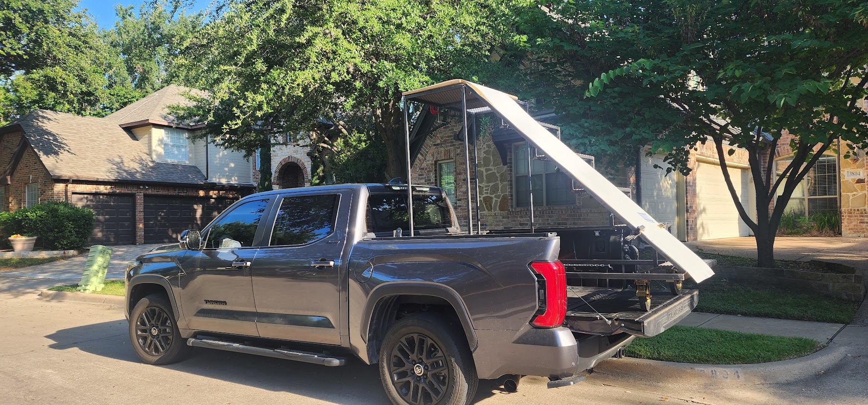
Prototype loaded in pickup truck with slide extending past tailgate

Open on YouTube

Friday, May 8, 2026

May 8, 2026 – Ready for the First User Test

The prototype has reached an important milestone.

After weeks of designing, welding, and making adjustments in the workshop, it's finally ready to leave the shop and be evaluated by the people it was built for.

In the next few days, I'll be taking the prototype to the high school so the band director and a group of students can put it through its first real-world test. Up until now, every decision has been based on engineering, experience, and educated guesses. It's time to replace those guesses with actual feedback.

There are several questions I'm hoping this testing session will answer:

  • Does the slide angle feel comfortable, or is it too steep?
  • Can students move naturally from the stairs onto the platform and then onto the slide?
  • Should the slide extend slightly above the platform to make getting seated easier?
  • Would a handle or grab bar help students transition onto the slide?
  • Does the top platform feel stable and comfortable to stand on?
  • Would removing a step and lowering the platform improve confidence?
  • Are there any unexpected interactions with uniforms or costumes, such as students catching clothing while sitting on the steps?

These are the kinds of questions that are difficult, if not impossible, to answer in a CAD model or workshop. The whole purpose of building a prototype is to discover what works, what doesn't, and what needs to change before investing the time and materials to build eleven more.

I'm looking forward to seeing students interact with the prop for the first time. No amount of planning can replace watching real users use something you've built.

We'll soon find out how close we are.

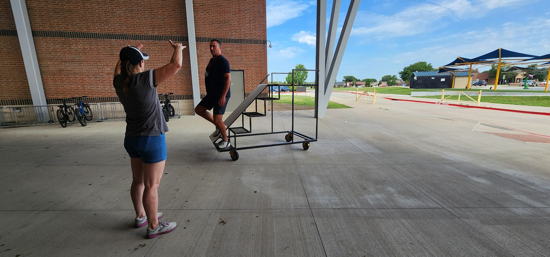
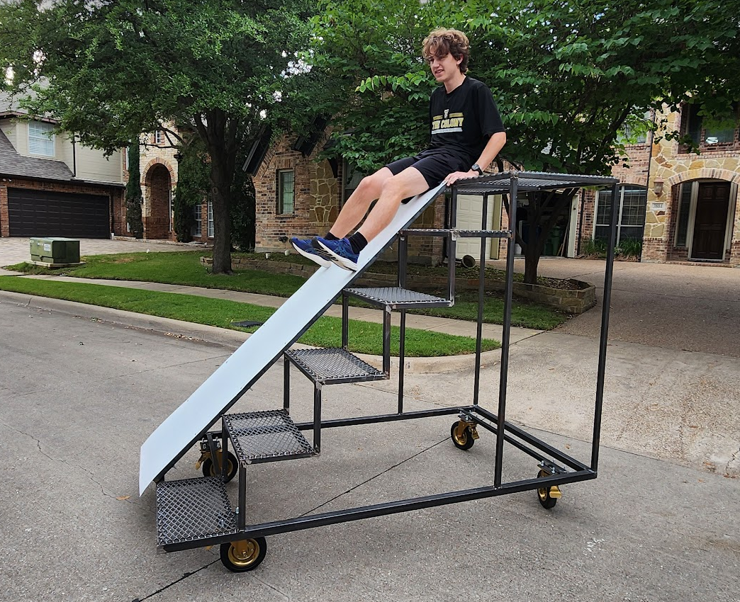
Student testing slide transition on prototype at band camp

Open on YouTube

Monday, April 13, 2026

April 13, 2026 – Show Reveal Parent/Student Meeting

Write-up coming soon.

Sunday, April 12, 2026

April 12, 2026

I've built one prop based on the design we discussed and attached photos along with a video link for your review. I estimate the cost at approximately $700 per prop, which includes the metal, 5 × 10 4 mm coroplast, slide material, and wheels.

With the current budget, we could build 12 of these, along with the additional stage piece and coroplast for up to 10 front screens. This would not leave room in the budget for coroplast for the back screens. I also plan to reuse the wheels from the back screens on the stair props to help offset some costs.

A few observations:

  • I'm still evaluating whether the current wheel placement provides enough stability. The wheels are set 6 in. in from each corner to prevent them from protruding when they swivel, to avoid interference when props are placed side by side.
  • I'm still determining the best material to cover the plywood to create the slide.
  • The current slide angle may be too steep.
  • Still need to add the handles for moving the prop.
  • Still need to add additional bracing.
  • All four wheels will be locking; I just only had 2 locking pair today when I finished the prop.
  • The final height from ground to top of platform is 69 inches.

Open on YouTube

Saturday, April 11, 2026

April 11, 2026 – It Finally Looks Like a Staircase

This was one of those shop days where the project seemed to leap forward.

Up until now, I'd been building individual subassemblies: the base, platform, stair sides, and wheel assemblies. Today was the day many of those pieces finally came together into something that actually looked like the prop we'd been designing for the past two months.

I started by finishing the stair frames, completing the structural framework that would support the expanded metal treads.

Next came cutting the expanded metal for the platform and each stair tread. This is one of those jobs that always takes longer than expected. Not only does each piece have to be cut to size, but every edge needs to be cleaned up afterward. Freshly cut expanded metal is incredibly sharp, and the last thing I want is students or volunteers getting cut on an unfinished edge.

With those pieces prepared, it was time for the exciting part.

The platform was welded onto the base frame, and the completed stair assembly was welded between the base and platform. For the first time, the prototype stood upright as a single structure.

After weeks of cutting, fitting, grinding, and welding individual parts, I could finally climb the stairs and stand on top of the platform.

There's always something satisfying about reaching this stage of a prototype. The CAD model has become reality, and all of the dimensions, proportions, and design decisions that existed only on a computer screen can finally be experienced in full scale.

The prototype was still far from finished. The slide hadn't been installed yet, and there were still details to work through before it would be ready for testing. But for the first time, it actually felt like a staircase instead of a collection of metal parts.

Days like this make all the repetitive cutting and fabrication worthwhile.

Open on YouTube

Thursday, April 9, 2026

April 9, 2026 – Making Progress One Evening at a Time

Another evening in the Maker At Play workshop.

Not every shop session is an all-day marathon. Sometimes it's just a couple of hours after work, but those shorter sessions still move the project forward.

Tonight's focus was on the wheel assemblies. I welded the wheel mounting plates to their support brackets and then welded those assemblies into the base frame. While they may not be the most noticeable parts of the finished prop, the wheels are one of its most important features. These props will be pushed all over the football field during rehearsals and performances, so the mounting points need to be strong enough to withstand constant movement and the occasional less-than-gentle handling.

One of the nice things about this stage of the project is that the individual subassemblies are finally starting to come together. Pieces that had been sitting separately on the welding table are now becoming part of the actual structure.

There wasn't a dramatic before-and-after transformation by the end of the night, but that's often how these weekday shop sessions go. A few more welds completed. A few more pieces checked off the list. A little less work left to do.

Slow, steady progress continues on the prototype.

Open on YouTube

Wednesday, April 8, 2026

April 8, 2026 – Seeing the Shape of the Prop

A Wednesday night in the Maker At Play workshop.

I decided to spend a few hours after work making more progress on the prototype. Sometimes the weekday shop sessions are short, but they can still move a project forward in meaningful ways.

I started by adding an additional brace to the top platform to improve its rigidity. With that complete, I turned my attention back to the stair assemblies. Before I could continue building them, I needed to grind down the welds on the stair sides to prepare them for the cross supports that would eventually tie everything together.

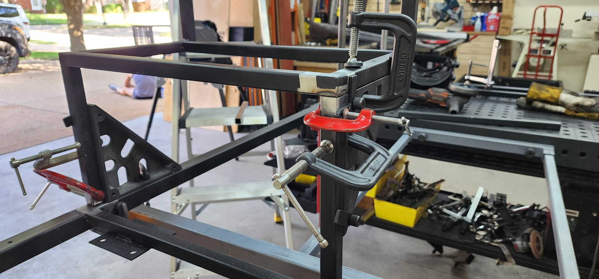
Once the weld cleanup was complete, I joined the two stair sides together with the first pair of cross pieces. This was the moment when the individual stair components began transforming into an actual staircase.

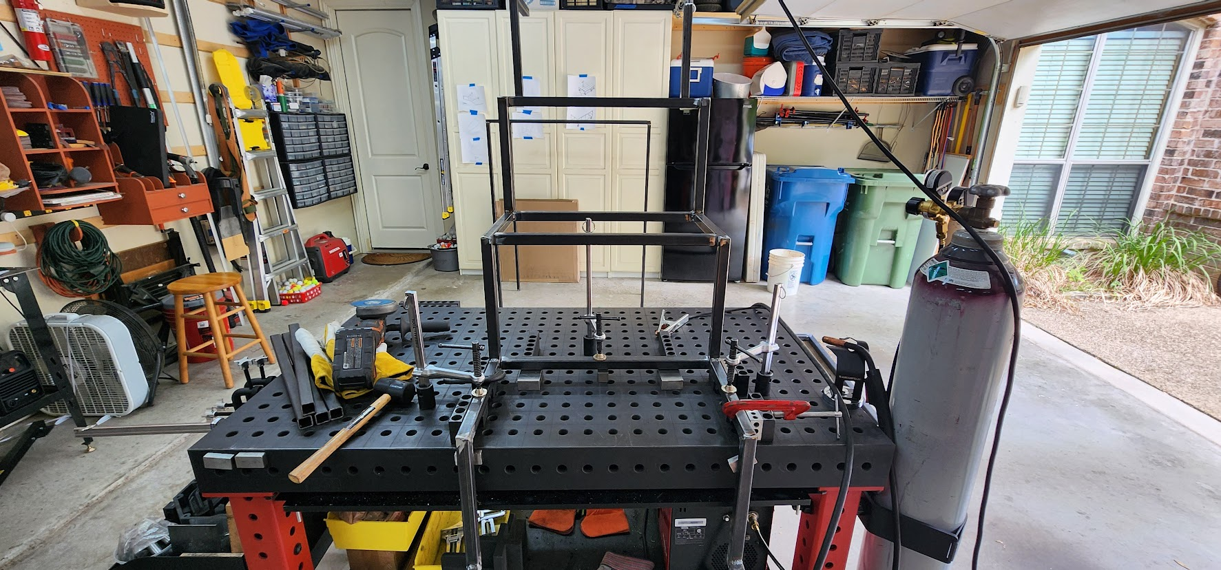
As usual, the Fireball welding table played an important role. I used it to fixture the stair assemblies and keep everything square while welding the cross supports into place.

This step also revealed one of the lessons that prototypes are supposed to teach.

My original approach had been to fully weld the stair sides first and then connect them together later. While that looked reasonable in CAD, reality had other plans. As the welds cooled, the stair sides moved just enough that not every angle remained perfectly square. The differences were small, but when it came time to connect the two sides together, those little deviations started to add up.

Nothing was dramatically wrong, but it became clear that this probably wasn't the manufacturing approach I would want to use for the full production run. Fortunately, with a little persuasion, clamps, and adjustment, everything came together.

Before wrapping up for the evening, I performed another dry fit of the base, platform, and stair assembly. This gave me my best look yet at how the major pieces would relate to one another.

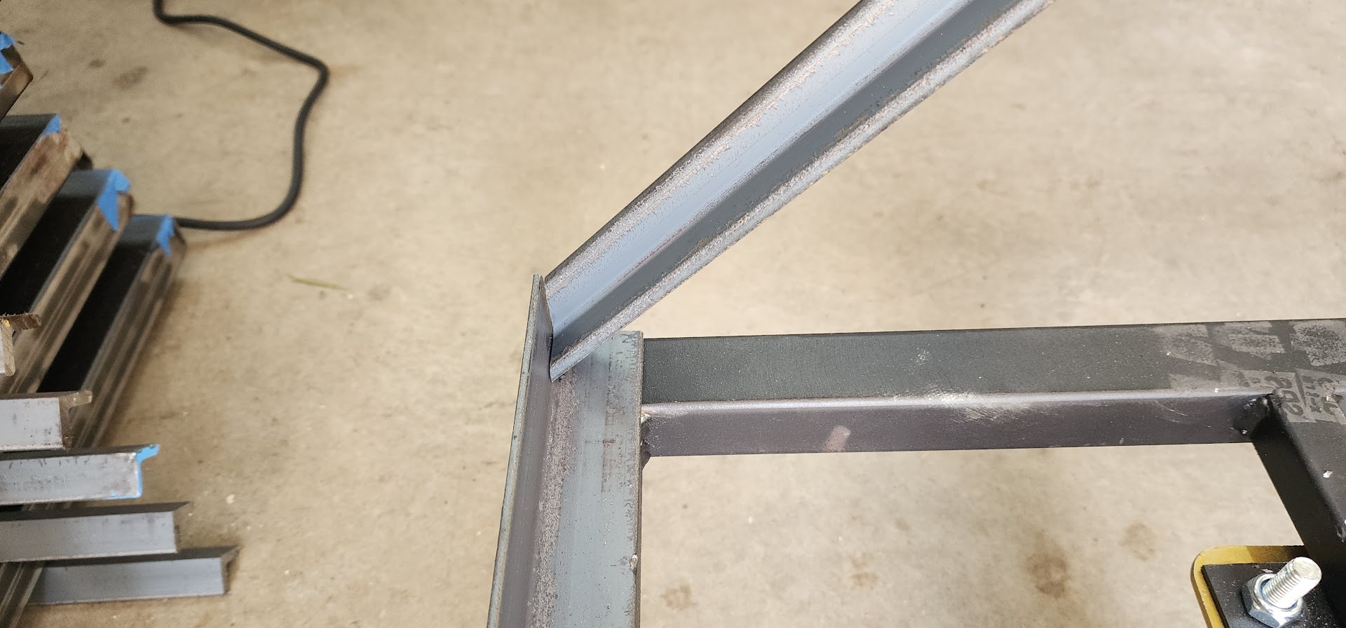
I also laid out a piece of angle iron that will eventually form the side support for the slide. For the first time, I could start visualizing the actual slide angle and get a feel for how the descent might look and function.

Dry fit of base, platform, stair assembly, and slide angle iron in workshop

Open on YouTube

Overall, it was a relatively short weekday session, but a productive one. The prototype continued doing exactly what it was supposed to do: revealing small issues, validating design decisions, and slowly turning a collection of metal parts into a prop.

Saturday, April 4, 2026

April 4, 2026 – Wheels, Platforms, and Practical Problems

Another Saturday in the Maker At Play props workshop.

Band props provide me with one large maker project every year, and each season brings its own unique challenges. I am still focused on building and validating the prototype for what will become the show's primary prop.

Today's work centered on the platform that forms the top of the staircase. This platform sits approximately five feet above the ground and serves as the transition point between climbing the stairs and sliding back down.

I started by cutting the four vertical legs to length, prepping the ends for welding, and attaching them to the rectangular top frame that was built during the previous work session. With that assembly taking shape, my attention shifted to another important design challenge: wheel placement.

At first glance, mounting the wheels directly at the corners seems like the obvious solution. It would maximize stability and make the wheel locks easy to access. However, these props are expected to move frequently during the performance and will often be positioned close together on the field.

Because of that, I didn't want the wheels extending beyond the footprint of the prop where they could interfere with neighboring props. The same concern applies during transportation. These props will travel side-by-side in a box truck, and protruding wheels could make loading, unloading, and packing far more difficult.

In fact, this transportation requirement influenced the overall dimensions of the prop. Rather than making the base a full 48 inches wide, I reduced it to 46 inches. That small change provides a little extra clearance when placing two props side-by-side in an 8-foot-wide box truck while having virtually no impact on the usability of the prop itself.

Once I settled on a preliminary wheel layout, I moved over to the milling machine and fabricated four wheel mounting plates, complete with mounting holes. These plates will be ready to weld onto the frame during the next work session once the final wheel locations are confirmed.

To wrap up the day, I set one of the completed stair runners next to the platform assembly. For the first time, I could begin to see the actual proportions of the staircase taking shape outside of Fusion 360. It wasn't assembled yet, but it was enough to get a feel for how the finished prop might look and function.

Stair runner leaned against platform assembly showing full prop proportions

Open on YouTube

Progress on a prototype can sometimes feel slow. There are lots of small decisions, measurements, and fabrication steps that don't immediately produce something recognizable. But each one helps reduce risk and improve the design before committing to the full production run later this summer.

Slow and steady progress.

Sunday, March 29, 2026

March 29, 2026 – Building the Foundation

Another good day in the Maker At Play props workshop.

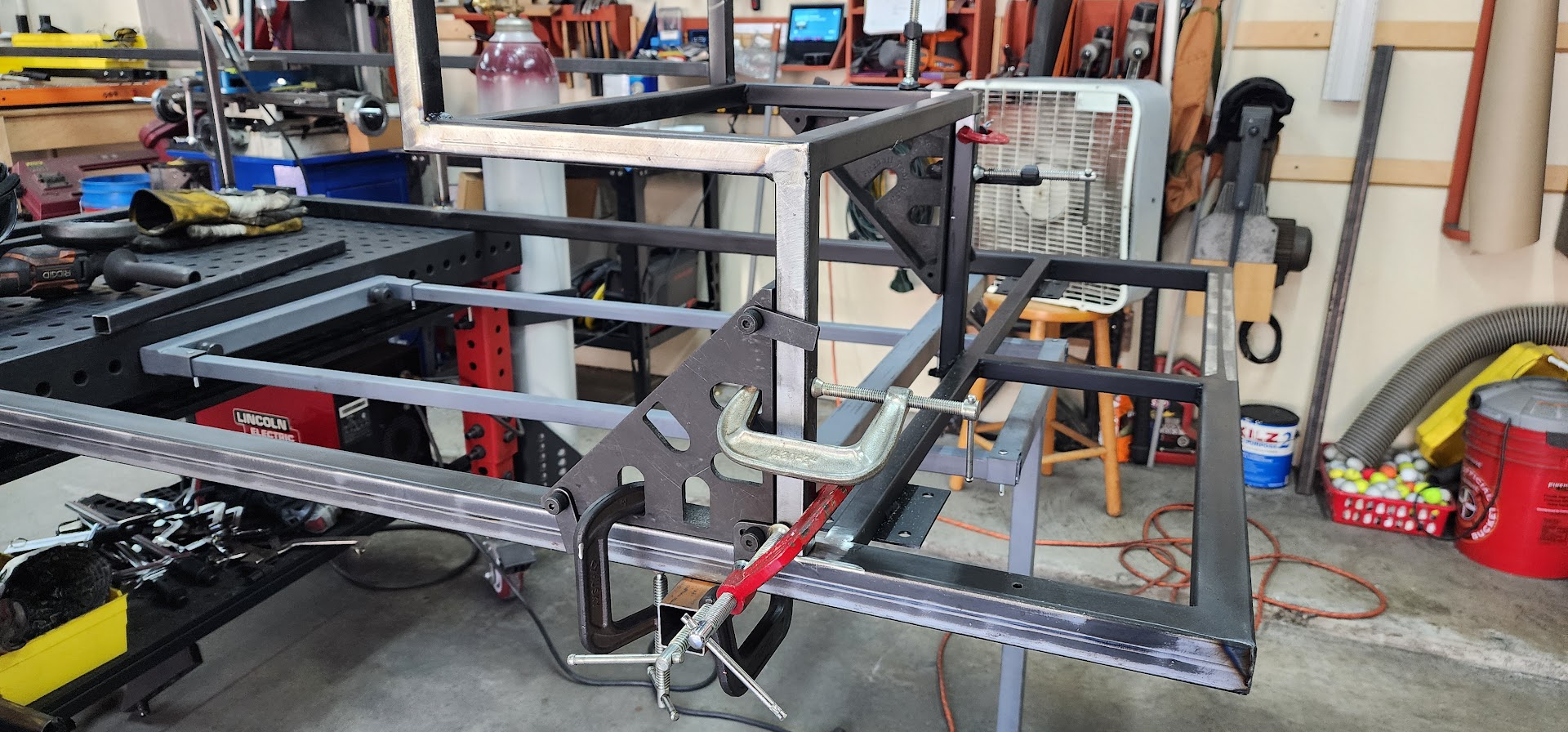
Today's focus was continuing work on the prototype. While the stairs tend to get most of the attention, every prop needs a solid foundation. I spent the day cutting and welding the 1.5-inch square tubing that would form the base frame. This structure will eventually support the entire prop and provide mounting points for the casters that allow it to move around the field.

For the base frame, I selected Steel Square Tube A500/A513 (Welded) 1.500" x 1.500" x 0.083". The larger tubing adds rigidity to the structure and was a material choice I felt confident about because it is the same tubing I used for last year's stages. Those stages spanned eight feet with very little noticeable flex, so I knew it would provide a solid foundation for these props.

The remainder of the prop uses Steel Square Tube A500/A513 (Welded) 1.000" x 1.000" x 0.083", which offers a good balance of strength and weight. For the slide supports, I chose Mild Steel Hot Rolled Angle 1.000" x 1.000" x 0.250", which should provide a sturdy attachment point for the slide surface while keeping the overall design relatively simple.

I also cut and welded the top platform, which measures 46 inches by 24 inches and is built from 1-inch square tubing. Like many of the assemblies so far, the Fireball welding table played a major role in keeping everything square and making assembly go much faster.

Open on YouTube

One fabrication detail I've become increasingly particular about over the years is how I finish the ends of tubing. Rather than leaving open tube ends, I cut 45-degree miters on the corners so the joints close cleanly. Structurally, leaving the ends open is perfectly acceptable for many applications, and that's how I built some of my earlier props.

Visually, however, open tube ends always bothered me.

As I've gained more fabrication experience, I've learned that the small details often make the biggest difference. Most people watching a marching band performance will never notice whether a piece of tubing has an open end or a mitered corner. But collectively, those little details contribute to the overall quality of the finished prop.

A prototype isn't just about testing dimensions and functionality. It's also an opportunity to refine construction techniques before committing to a dozen copies of the same structure.

By the end of the day, there wasn't much that looked like a staircase yet. Instead, there was a growing collection of accurately cut and welded components that would eventually become one.

While the visual progress was modest, the lessons learned were significant. Every cut and weld was helping answer an important question: could this design be built efficiently not just once, but a dozen times?

Saturday, March 21, 2026

March 21, 2026 – Time to Build a Prototype

Up to this point, the staircase props had only existed as ideas, sketches, and Fusion 360 models. With the metal now acquired, it was time to build a physical prototype and find out how well those ideas translated into reality.

While Fusion 360 is an incredible tool, there are some questions that can only be answered by building something and putting hands on it. Before committing to a full set of props, I wanted to validate several assumptions:

  • Are there any challenges cutting and welding the parts as designed?
  • How strong is the structure, and does the frame flex under weight?
  • How does the stair spacing feel when walking up and down?
  • Is the slide angle comfortable, or is it too steep?
  • How does it feel to stand on the top platform?
  • How natural is the transition from standing to sitting and sliding?
  • Is the wheel spacing wide enough to feel stable without the casters extending beyond the frame and interfering with adjacent props?

In many ways, this prototype wasn't about proving the design would work. It was about discovering everything I got wrong.

The first day's work focused on cutting and welding the pieces that would make up the stair structure. One of the best investments I've made in my workshop is my Fireball welding table. Within minutes I was able to set up fixtures that held the tubing square, making it easy to repeatedly weld the 90-degree joints needed for each step.

My initial plan was to build the two stair "runners" first and then weld the cross members between them later. On paper, that seemed like the fastest approach.

As I started assembling the pieces, however, I began to realize that what looked good in CAD wasn't necessarily the best way to manufacture twelve of these things.

That's one of the hidden benefits of a prototype. Sometimes you're testing the design. Sometimes you're testing the build process. And occasionally you discover that the real problem isn't the prop at all, it's how you planned to put it together.

By the end of the day, I had parts coming together and a much better understanding of what the fabrication process would look like. More importantly, I was already rethinking how I would approach building the full set.

The prototype was doing exactly what it was supposed to do.

Tuesday, February 24, 2026

February 24, 2026 – First Design Review

Just two days after sending the initial drawings, I received the first round of feedback from the band director and show designer.

The response was encouraging. The overall concept was on the right track, and the feedback focused on refining the design rather than rethinking it. That's always a good sign during the early stages of a project.

The biggest suggestion was to make the top platform larger so students would have more room to safely turn around before descending the stairs or slide. There was also discussion about adding handles to make the props easier to maneuver around the field during performances and rehearsals.

One of the things I enjoy most about designing in Fusion 360 is how quickly ideas can be tested and updated. Instead of trying to explain changes with sketches or descriptions, I was able to make the modifications directly in the model and generate updated renderings the same day.

The revisions included:

  • Expanding the top platform to 2 feet deep
  • Extending the overall base width from 6 feet to 7 feet
  • Adding 12-inch handles on each side approximately 4 feet above the ground
  • Confirming the platform height would remain below the 6-foot limit once the caster height was accounted for

Within a few hours of receiving the feedback, I had an updated model ready for review.

This is one of the reasons I like creating 3D models early in the process. A drawing turns abstract ideas into something concrete, and once everyone can see the same thing, improvements happen quickly. Each round of feedback builds on the last, gradually transforming an idea into a practical design.

At this point, the concept was beginning to feel real. We had moved beyond discussing "stair props" and were starting to define the actual structure that performers would eventually use on the field.

Sunday, February 22, 2026

February 22, 2026 – First Staircase Mockup

I spent most of the weekend in Fusion 360 sketching out what the staircase/slide props might look like based on our kickoff meeting.

One of the biggest challenges with marching band props is translating an artistic vision into something that can actually be built, transported, moved around a football field, and safely used by students. This first design was my attempt at turning the "Escher-inspired staircase" concept into something tangible.

Based on my understanding from our initial discussions, I modeled a prop that was:

  • 6 feet wide
  • 4 feet deep
  • 6 feet tall
  • Six steps from the ground to the top platform
  • A staircase on one side and a slide on the other
  • Designed as matching mirrored pairs so multiple props could be positioned back-to-back across the field, creating continuous pathways for performers to march across the structures
  • Mounted on casters so it could be moved during the show

The stairs were designed with 1-foot-deep treads and 1-foot rises. At this stage, I was still assuming full-height steps and a fairly traditional staircase layout.

The slide surface would eventually be covered with a material that would allow performers to slide safely during the performance.

Once the first renderings were complete, I sent them to the band director and show designer for feedback. One thing I've learned over the years is that a visual model is worth far more than a verbal description. Everyone can hear the same idea and imagine something completely different. A 3D model gives everyone a common starting point, making it much easier to discuss what is working, what isn't, and where the design should go next.

At this point, we still didn't know exactly how many props would be needed or what refinements might be required. The goal wasn't to have the final answer. The goal was to turn an idea into something people could see, react to, and build upon.

This was the first real glimpse of what would eventually become this season's signature prop.

Tuesday, February 17, 2026

February 17, 2026 – Props Kickoff

Today we had our first props kickoff meeting with the band director and show designer. What's unusual about that? It's only February, almost two full months before show reveal.

Every marching season people ask if I get an early look at the show and props before everyone else. Up until this year, the answer was always no. I found out about the show and the prop concepts at show reveal just like everyone else.

For some reason, in my final year as a band parent with a student in the program, I got invited into the conversation much earlier. My guess is that this year's props are much more integrated into the drill and visual design, which meant we needed a longer runway for planning and construction.

One important note for anyone reading this: while this post is dated February 17, it wasn't actually published until June, nearly two months after show reveal. No secrets were leaked in the making of this blog.

The inspiration for this year's show, and therefore the props, comes from M. C. Escher's famous lithograph Relativity (often referred to as the "crazy stairs" artwork). The early concept calls for 8 to 12 staircase props spread across the field, built as mirrored pairs.

The initial design ideas discussed included:

  • Staircase structures approximately 4 feet wide and 6 feet tall
  • A combination of stairs and slides
  • Slides that performers can actually use during the show
  • Custom-cut 4mm coroplast skins shaped to match the stair geometry
  • Potential backfield props if the stair structures alone don't create enough visual impact
  • A small number of sideline screens, though that was still undecided
  • Two dock-themed stages flanking the front ensemble

The good news is that we'll be able to reuse the stages we built last season, which should save both time and budget.

At this point, nothing is finalized, but it looks like we'll be building somewhere between 8 and 12 staircase/slide props. Even in this early meeting, it was clear that this year's project would be larger and more integrated into the show design than anything we've tackled before.

Time to start sketching.